FUNCTIONAL OPERATION ROI-S04488
2-28
28 pages
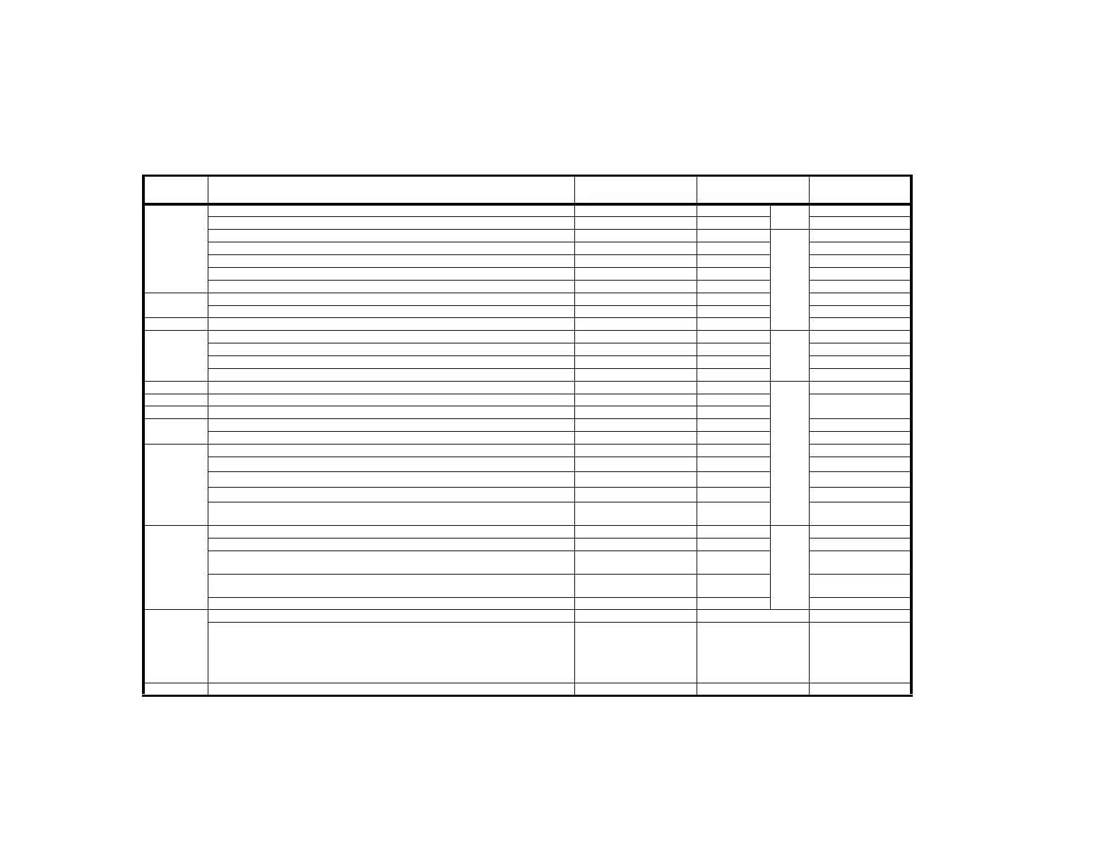
Table 2-3 Alarm Indication and Reporting
DETECTING
CIRCUIT
ALARM CONDITION ALARM INITIATED
LED INDICATION
ON IDU
REMOTE ALARM
REPORT *1
INTFC
AIS signal is sent AIS SEND —
IDU*2
—
AIS (all logic “1”) is received AIS RCVD — —
Input data stream is lost INPUT LOSS TX ALM ( )
IDU
TX ALM ( )
Transmitter clock is lost TX CLK LOSS TX ALM ( ) TX ALM ( )
Receiver clock is lost RX CLK LOSS RX ALM ( ) RX ALM ( )
Output data stream is lost OUTPUT LOSS RX ALM ( ) RX ALM ( )
Setting error of traffic channel assignment for usage CHANNEL USAGE ERROR TX ALM ( ) TX ALM ( )
SW BOARD
TX 1/2 CLK is lost TX IN CLK LOSS1/2 TX ALM 1/2 TX ALM 1/2
RX1/2 CLK is lost RX IN CLK LOSS1/2 RX ALM1/2 RX ALM 1/2
LAN INTFC FE link down, selectable FE LINK DOWN LINK LAN INTFC ALM
WS INTFC
Wayside input data stream is lost WS INPUT LOSS TX ALM ( )
IDU*3
TX ALM ( )
Wayside AIS is received WS AIS RCVD TX ALM ( ) TX ALM ( )
Wayside output data stream is lost WS OUTPUT LOSS RX ALM ( ) RX ALM ( )
Wayside AIS is transmitted WS AIS SEND RX ALM ( ) RX ALM ( )
WS INTFC Wayside channel usage error, selectable WS CHANNEL USAGE TX ALM ( )
IDU
TX ALM ( )
DPU Output data stream or master clock signal is lost at the DPU (TX) circuit TX DPU ALM TX ALM ( )
TX ALM ( )
MOD VCO synchronization is lost at the MOD circuit MOD ALM TX ALM ( )
DEM
Carrier synchronization is lost DEM ALM RX ALM ( ) RX ALM ( )
IF input signal is lost DEM ALM RX ALM ( ) RX ALM ( )
DPU
Frame synchronization is lost at the DPU (RX) F SYNC ALM RX ALM ( ) RX ALM ( )
BER is worse than preset value (1 x 10
−3
)
HIGH BER ALM RX ALM ( ) RX ALM, ( ) BER ALM
BER is worse than preset value (1 x 10
−6
)
LOW BER ALM RX ALM ( ) RX ALM ( ), BER ALM
BER is worse than preset value (1 x 10
−3
, 1 x 10
−4
, 1 x 10
−5
or 1 x 10
−6
, selectable)
BER ALM RX ALM ( ) RX ALM ( ), BER ALM
CPU communication error between IDU and ODU OPR ALM
TX ALM ( )
RX ALM ( )
TX ALM( )
RX ALM ( )
ODU
Transmitter RF power decreases 3 dB from normal TX PWR ALM TX ALM ( )
ODU
TX ALM ( )
Receiver input level decreases from squelch level at ODU RX LEV ALM RX ALM ( ) RX ALM ( )
APC loop of local oscillator for transmitter or first local oscillator for receiver unlocks at ODU APC 1 ALM
TX ALM ( )
RX ALM ( )
TX ALM ( )
RX ALM ( )
APC loop of second local oscillator for receiver unlocks at ODU APC 2 ALM
TX ALM ( )
RX ALM ( )
TX ALM ( )
RX ALM ( )
IF signal from the IDU is lost at ODU IF INPUT ALM TX ALM ( ) TX ALM ( )
—
When the equipment is set to the Maintenance condition by PC. MAINT ALM MAINT MAINT ALM
When the equipment is set to the following condition by PC.
• FE loopback control condition
• NE loopback control condition
• MOD CW condition
• MUTE (TX output power) condition
• BER ALM >> AIS (off)
— MAINT ( ) —
SW BOARD OPR SEL No.1-No.2 switch is set to No.1 or No.2 position. MAINT ALM MAINT ( ) MAINT ALM