NEC PASOLINK installation procedure
January 2002
TERMINAL DESCRIPTION
LA PORT (D-sub Connector,15 Pins)
Pin 1
Pin 3
Pin 4
Pin 5
Pin 11
Pin 12
Pin 13
Pin 15
Pin 2,8 and 14
Control/Monitoring signal input/output from/to personal computer
TXD
RXD
RTS
CTS
LOCAL CTS
LOCAL RTS
LOCAL RXD
LOCAL TXD
Ground
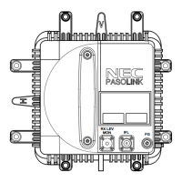
ODU
IF IN/OUT(N-P Connector)
RF IN/OUT
13 GHz PBR140
18 GHz PBR220
26 GHz PBR260
38 GHz PBR320
TX IF signal input and RX IF signal output
Danger: Do not disconnect the coaxial cable before turning off the power
switch on the IDU.
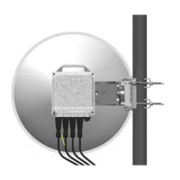
RF signal input/output from/to antenna.
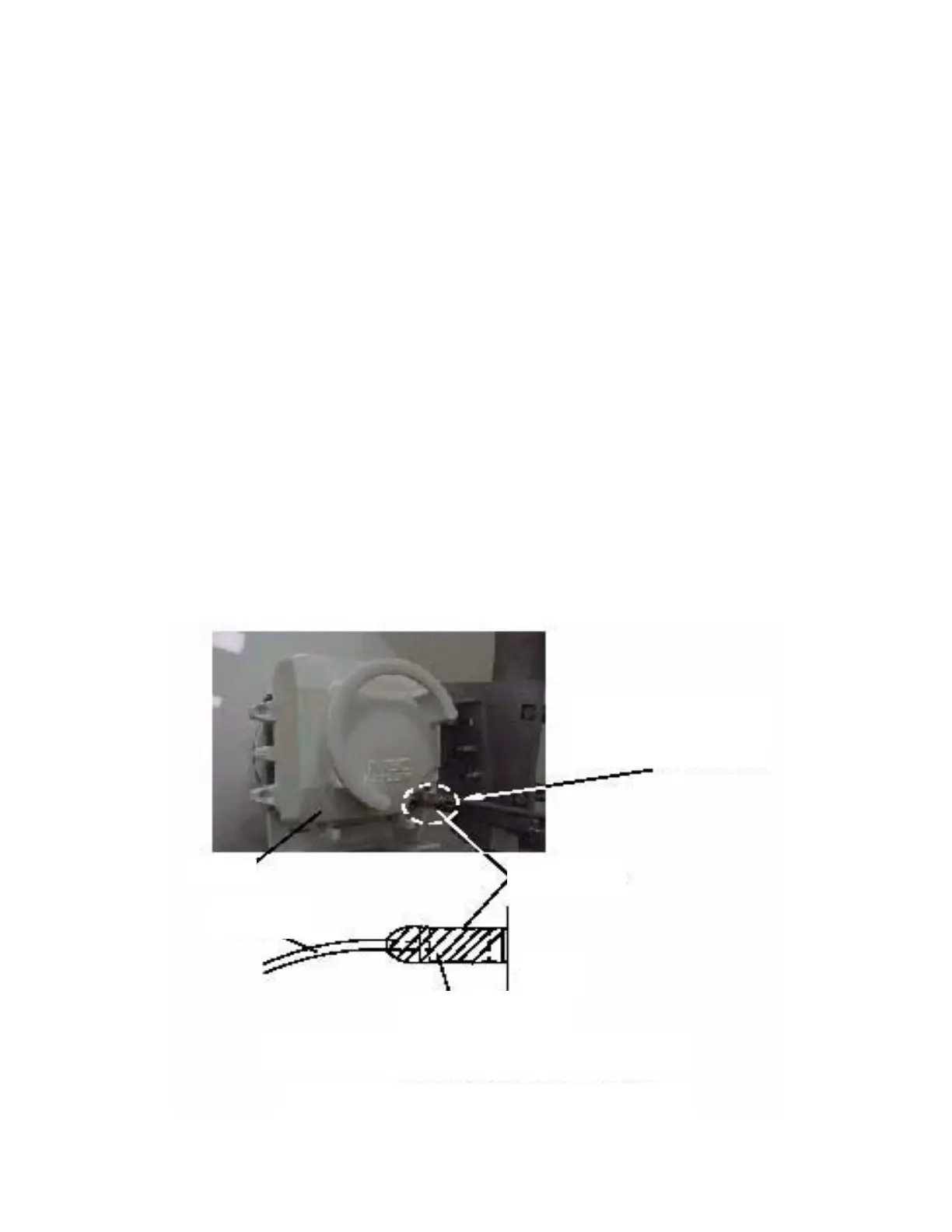
Waterproof Protection:
After cable connection, the following part shall be wrapped by self-bonding
tape for waterproof (see Following Fig. ),
This part shall be wrapped by
self-b onding tape for
waterproof.
IFL Connector
ODU
Self-bonding tape
IF CABLE
ODU
Note: the self-bonding tape shall be prepared by customer.
Location of connector for waterproof
aterproof Protection:
fter cable connection, the following part shall be wrapped by
elf-bonding
ape for waterproof (see Following Fig. ),