OPERATION ROI-S04488
3-20
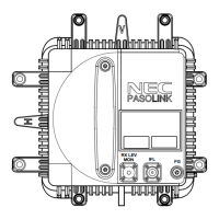
3.2 Controls, Indicators and Test Jacks
The controls and indicators and test jacks on the IDU (see Fig. 3-3) are
described as follows.
IDU indicator
Lights when:
• Input data stream of CH ( ) from DTE is lost,
• AIS (all “1”) signal of CH ( ) is received from DTE (selectable),
• TX/RX clock synchronization is lost at the DPU section,
• If a 2 MB is fed to a CH which is selected as "Not Used"
(selectable),
• If a 2 MB is fed to the WS CH after setting to "Not Used"
(selectable),
• AIS signal of CH ( ) is sent (depending on system requirement)
(selectable),
• Bipolar output pulse of CH ( ) is lost at the INTFC section,
• Carrier synchronization is lost at the DEM section,
• High bit error rate (High BER) is worse than preset value (1x10
-3
)
at the DPU section,
• BER is worse than preset value at the DPU section (1x10
-3
,
1x10
-4
, 1x10
-5
or 1x10
-6
, selectable),
• Frame synchronization is lost at the DPU section,
• VCO synchronization is lost at the MOD section,
• Output data stream or master clock signal is lost at the DPU(TX)
section,
ODU indicator
Lights when:
• Transmit RF power decreases 3 dB from normal at the ODU,
• Receiver input level decreases by a preset value from squelch level
at the ODU,
• APC loop of local oscillator unlocks at the ODU or,
• IF signal from the IDU is lost at the ODU,