ROI-S04488 OPERATION
3-29
3.3 Equipment Start-up and Shut-down
Procedure for equipment start-up and shut-down are described below.
3.3.1 Start-up
Test Equipment and Accessories Required
• Agilent 34401A Digital Multimeter (or equivalent) with Test Leads
Step Procedure
1 Check that the LINE IN voltage is between +20 V to +60 V/
−20 V to −60 V with the digital multimeter, before connecting
the power connector to the IDU,
Note: The range of DC power input depends on system
requirement.
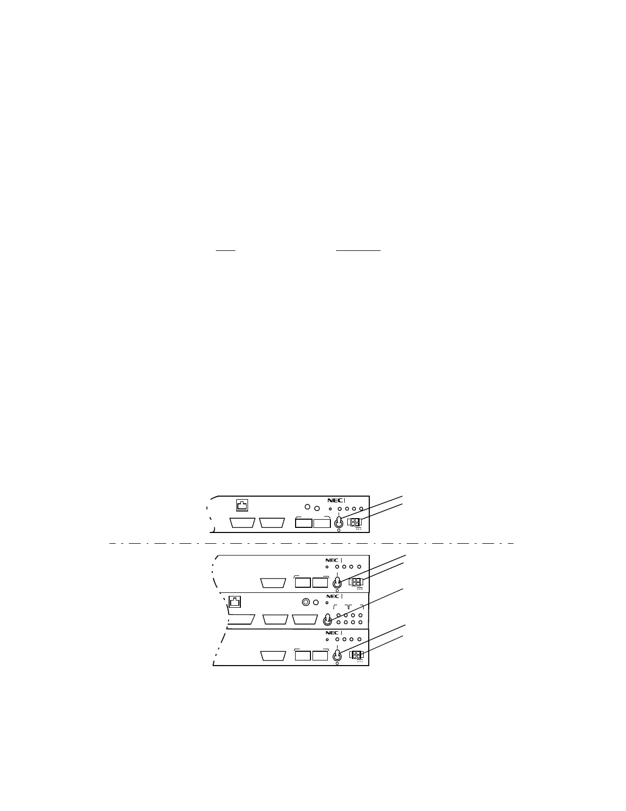
2 Turn on the POWER switch on the IDU (refer to Fig. 3-5),
Note: In 1+ 1 system,
When neither No.1 nor No.2 channel is working, first set
the OPR SEL No.1-No.2 switch on the IDU to neutral
position or No.1 or No.2 to be powered up side.
When either No.1 or No.2 channel is working, set the
OPR SEL No.1-No.2 switch on the IDU to the working
channel side, then, turn on the power switch of the not
working channel.
3 Allow equipment to warm up for at least 30 minutes.
Fig. 3-5 Front View of the IDU for Powering Up
RESET
IDU
ODU
PWR
PASOLINK
MAINT
SELV
−
+
LA PORT
LA PORT
DSC/ASC LA PORT
NMS/RA
CALL
OPR
FUSE (7.5A)
FUSE (7.5A)
EOW
MS LAN
RX
RXTXTX
OPR ALM
SEL
No.1
No.2
1
2
−
PASOLI NK
RESET
RESET
IDU
ODU
PWR
PASOLINK
MAINT
SELV
−
+
LA PORT
NMS/RA
NMS LAN
CALL
RESET
MAINT
IDUODU
SELV
−
PWR
FUSE (7.5A)
EOW
PASOLINK
+
IDU for 1+0 System
IDU for 1+1 System
No.1 Power Switch
No.2 Power Switch
Power Switch
OPR SEL No.1 - No.2 Switch
LINE IN Connector
LINE IN Connector
LINE IN Connector