ROI-S04488 OPERATION
3-15
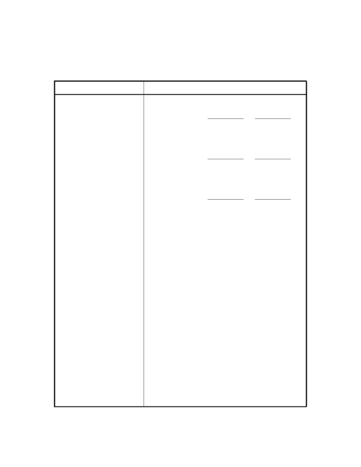
Pins 23 (COM), 24 (NO)
and 25 (NC)
Maintenance alarm output*
3
Between Between
Pins 23 and 24 Pins 23 and 25
Normal state : Open Closed
Alarm state : Closed Open
Pins 26 (COM), 27
(No. 2) and 28 (No. 1)
Switching answer signal output for transmitter
Between Between
Pins 26 and 27
Pins 26 and 28
No. 1 CH selection : Open Closed
No. 2 CH selection : Closed Open
Pins 29 (COM), 30
(No. 2) and 31 (No. 1)
Switching answer signal output for receiver
Between Between
Pins 29 and 30
Pins 29 and 31
No. 1 CH selection : Open Closed
No. 2 CH selection : Closed Open
Note:*
3
The BER threshold values and alarm items are set in
factory (default). To change the setting of alarm items
by the PC, refer to Section 3.4.1 "Alarm Table" of this
Manual.
AUX ALM
(D-sub Connector, 25 Pins)
Transmission network surveillance auxiliary
Note: When an optional PM CARD module is mounted,
following input/output terminals (Pins 1 to 21) are
used as housekeeping alarm/control interface.
Pin 1 Input 11
Pin 2 (G) Input 12
Pin 3 Input 21
Pin 4 (G) Input 22
Pin 5 Input 31
Pin 6 (G) Input 32
Pin 7 Input 41
Pin 8 (G) Input 42
Pin 9 Input 51
Pin 10 (G) Input 52
Pin 11 Input 61
Table 3-2 Interface Terminals and Jacks of 1+1 System (5/9)
Terminal Description