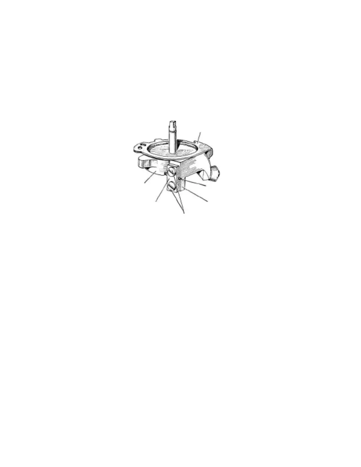
Preassembling of group Fig. 95.
Place the thin washer No. A26/3/9 (Fig. 96) above the already
prepared group, as shown in Fig. 94, so that the small hole " A
" of this washer is exactly above the hole " A " of assembly Fig. 94.
Place the washer on assembly Fig. 94 as shown in Fig. 96.
If during this assembly procedure the position of the hole in the
washer should move, check its position again and rectify it, if
necessary.
A 26/3/15
Round side of the
pulling drum No. C
(A26/3/6)
A
26/3/11
035080FDB
Fig. 95
End of spring No. A 26/1
11
Flat portion "0" of drum
No. C (A26/3/6)
Place the upper pulling drum No. C(A26/3/6), which acts as
a cover, over the already assembled group so that the flat por-
tion " O " of this drum (see Fig. 95) will rest lightly (without
force) against the spring No. A26/1/11. Tighten the spring
No. A26/1/11 to the drum No. C(A26/3/6) by means of the
small plate No. A26/3/11 and the two screws No. 035080FDB
(see Fig. 95). Tighten these two screws thoroughly.
NOTE: If the two brake shoes (Fig. 94) are assembled correct-
ly, the two holes " A " of the brake shoe No. A26/3/4 and of