N720 OpenLinux
Hardware User Guide
Copyright © Neoway Technology Co., Ltd
Pull USB_ID low before supplying power for USB_VBUS.
PCB Design Guidelines
Place filer capacitors on the USB_VBUS line as close to the pin of the module as possible and
the ESD component as close to the USB connector as possible.
Place the ESD triodes on USB_DP and USB_DM lines as close to the USB connector as
possible.
USB_DM and USB_DP traces should be routed in differential mode, and the differential
impedance of the transmission line is 90Ω.
Isolate USB traces from traces of other signals by connecting their grounds to main ground.
3.3.3 USIM
Compatible with 1.8V/3V UIM card
A 10 kΩ resistor is required between
USIM1_VCC and USIM1_DATA.
A pull-up resistor is recommended
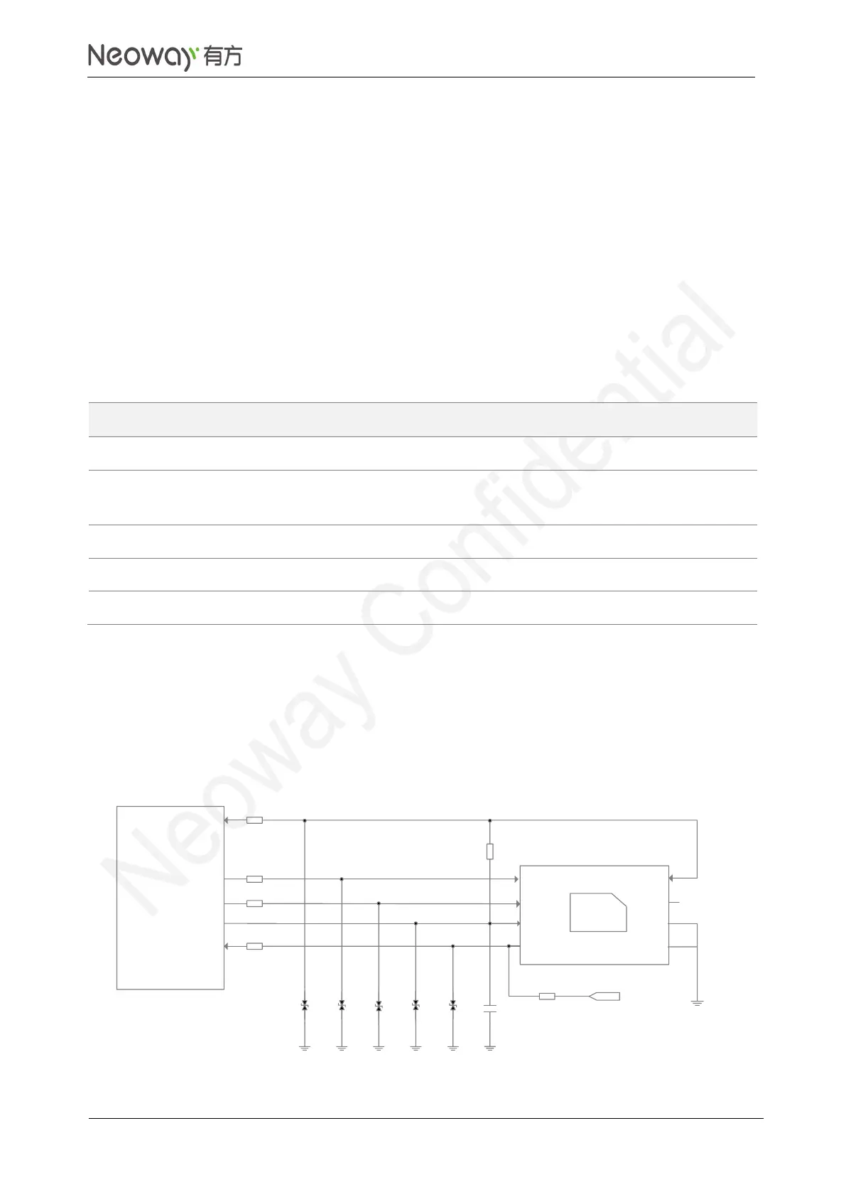
N720 OpenLinux provides one USIM1 interface by default. USIM2 interface is a multiplex function of
Ethernet interface and compatible with 1.8V/2.85V USIM card. For details, see Section 3.7 MUX
Interfaces. Figure 3-15 shows the reference design of the USIM card interface.
Figure 3-15 Reference design of USIM card interface
1uF
CLK
RST
VCC
VPP
GND
USIM card
DATA
GND
USIM-DET
20Ω
47kΩ
VDD_1P8
USIM_DATA
USIM_CLK
USIM_RESET
USIM_VCC
USIM_DET
N720 module
20Ω
20Ω
20Ω
10kΩ
R1
R2
R3
R4
R5
R6
C1
ESD1 ESD2
ESD3 ESD4 ESD5