N720 Hardware User Guide
Copyright © Neoway Technology Co., Ltd 16
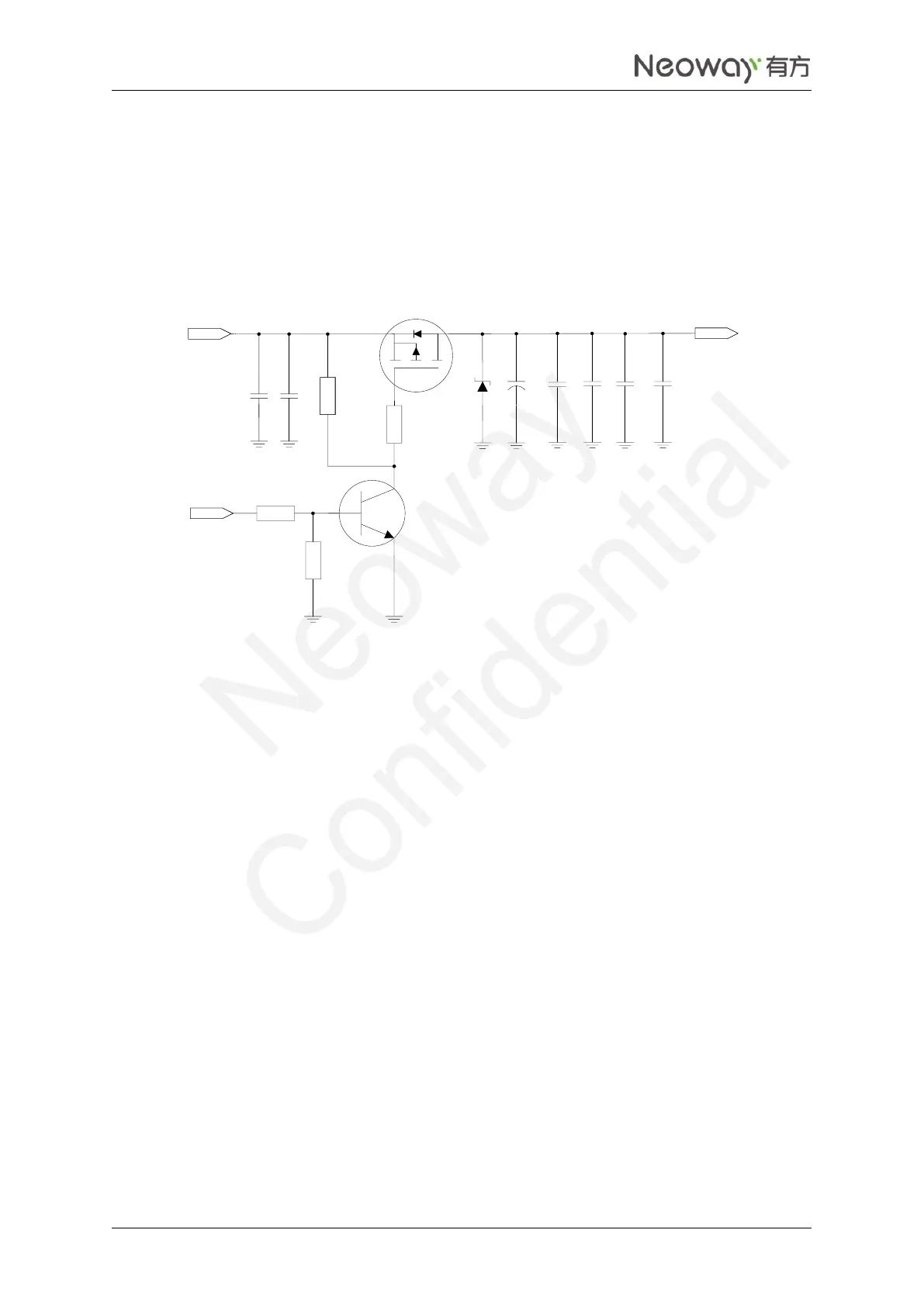
The alternative way is to use an enhancement mode p-MOSFET to control the module's power, as shown
in Figure 2-5. When the external MCU detects the exceptions such as no response from the module or the
disconnection of GPRS, power off/on can rectify the module exceptions.
In Figure 2-5, the module is turned on when PWR_EN is set to high level.
Figure 2-5 Reference design of power supply controlled by p-MOSFET
VCC_IN_3.9V
VBAT
10K
100K
33 pF
10 uF
2K
10K
0.1 uF
Q1
R4
C1
C2
C4
C5
C7
R1
R2
10 uF 0.1 uF
R3
Q2
TVS
5V
470 uF
C3
C6
100pF
S
G
D
PWR_EN
Q2 is added to eliminate the need for a high enough voltage level of the host GPIO. In case that the GPIO
can output a high voltage greater than VCC_IN - |VGS (th)|, where VGS (th) is the Gate Threshold
Voltage, Q2 is not needed.
Reference components:
Q1 can be IRML6401 or low Rds (on) p-MOSFET, which has higher, withstand voltage and drain
current.
Q2: a common NPN tripolar transistor, e.g. MMBT3904; or a digital NPN tripolar transistor, e.g.
DTC123. If digital tripolar transistor is used, delete R1 and R2.
C3: 470 μF tantalum capacitor rated at 6.3 V, or 1000 μF aluminum capacitor. If lithium battery is
used to supply power, C3 can be 220 μF tantalum capacitor.
Power Supply Protection
Add TVS diodes (VRWM=5 V) on the VBAT power supply, especially in automobile applications. For
some stable power supplies, Zener diodes can decrease the power supply overshoot. SMF5.0AG from
ONSEMI is an option.