N720 Hardware User Guide
Copyright © Neoway Technology Co., Ltd 29
2.7 AUDIO Interfaces
The AUDIO function can be implemented by connecting PCM, I2S_MCLK and I2C signals to an external
Codec chipset.
2.7.1 PCM
Leave this pin unconnected if it is not used.
Leave this pin unconnected if it is not used.
Leave this pin unconnected if it is not used.
Leave this pin unconnected if it is not used.
Leave this pin unconnected if it is not used.
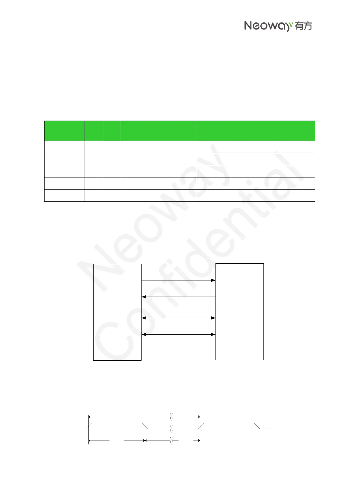
The PCM interface supports master and slave mode. Its reference high level is 1.8V. The following figure
shows the PCM connection.
Figure 2-23 PCM connection
PCM_DOUT
PCM_DIN
PCM_SYNC
PCM_CLK
N720 module
CODEC shipset
PCM_DIN
PCM_DOUT
PCM_SYNC
PCM_CLK
The PCM clock can be up to 2048 KHz. The following figures show the PCM timing.
Figure 2-24 PCM synchronization timing
PCM_SYNC
t(sync)
t(syncd)
t(synca)