N720 Hardware User Guide
Copyright © Neoway Technology Co., Ltd 37
Big RF solder pad can result in great parasitic capacitance, which will affect the antenna performance.
Remove the copper on the first and second layers under the RF solder pad.
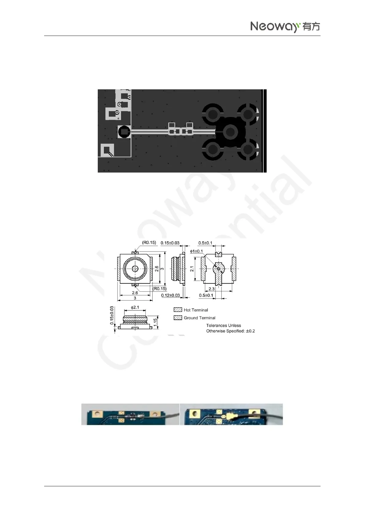
Figure 3-2 Recommended RF PCB design
To adopt RF antenna connections, the GSC RF connector MM9329-2700RA1 from Murata is
recommended. Figure 3-3 shows the encapsulation specifications.
Figure 3-3 Encapsulation specifications of Murata RF connector
RF antenna can also be connected to the module by soldering. In this manner, ensure proper soldering in
case of damage that lowers RF performance. Figure 3-4 shows the pictures of these two connections.
Figure 3-4 RF connections