N720 Hardware User Guide
Copyright © Neoway Technology Co., Ltd 32
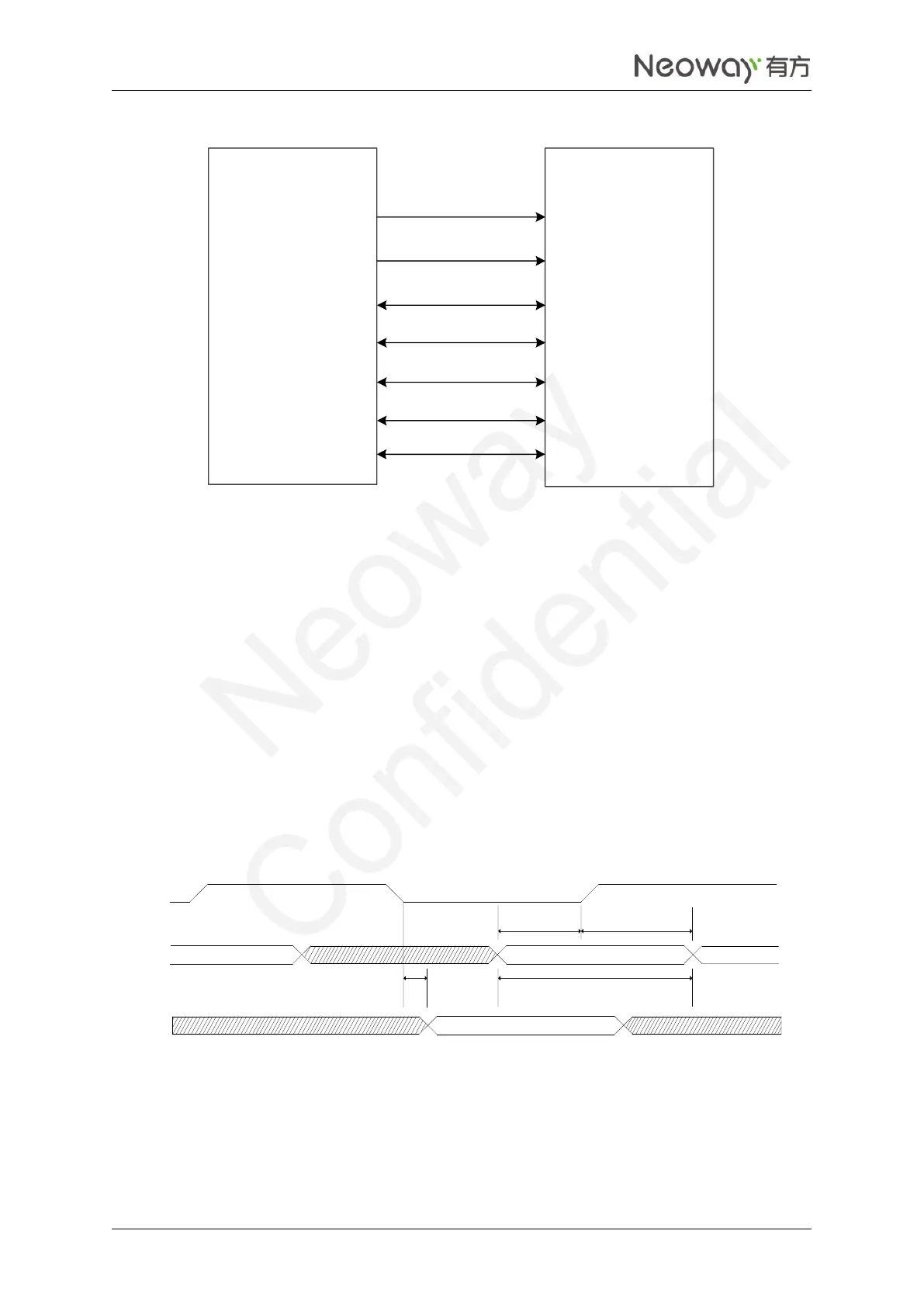
Figure 2-27 SDIO connection
N720
WLAN
chipset
SDIO_CLK
SDIO_CMD
SDIO_DATA0
SDIO_DATA0
SDIO_DATA0
SDIO_DATA0
SDIO_CLK
SDIO_CMD
SDIO_DATA0
SDIO_DATA0
SDIO_DATA0
SDIO_DATA0
GNDGND
The CLK, CMD, DATA0, DATA1, DATA2, and DATA3 signals of SDIO are high-speed signals. On the
PCB, the route impedance should be limited to 50Ω and the traces should be laid on the inner layer and
not be across other traces. It is recommended to keep the traces of CMD, DATA0, DATA1, DATA2, and
DATA3 same length. The CLK trace should not be longer or shorter than the traces of other signals too
much and should be surrounded by ground.
The SDIO interface supports a maximum clock frequency of SDR 200 MHz or DDR 50 MHz, and it is
compatible DS, HS, SDR12, SDR25, SDR50, and SDR104.
The following figures and table shows the sequences and parameters of SDR and DDR modes
respectively.
Figure 2-28 SDIO SDR timing
SD_CLK
Read
Write
t(pddwr)
t(pdcwr)
t(cdvrd)
t(dvrd)
t(csurd)
t(dsurd)
t(chrd)
t(dhrd)