N720 Hardware User Guide
Copyright © Neoway Technology Co., Ltd 25
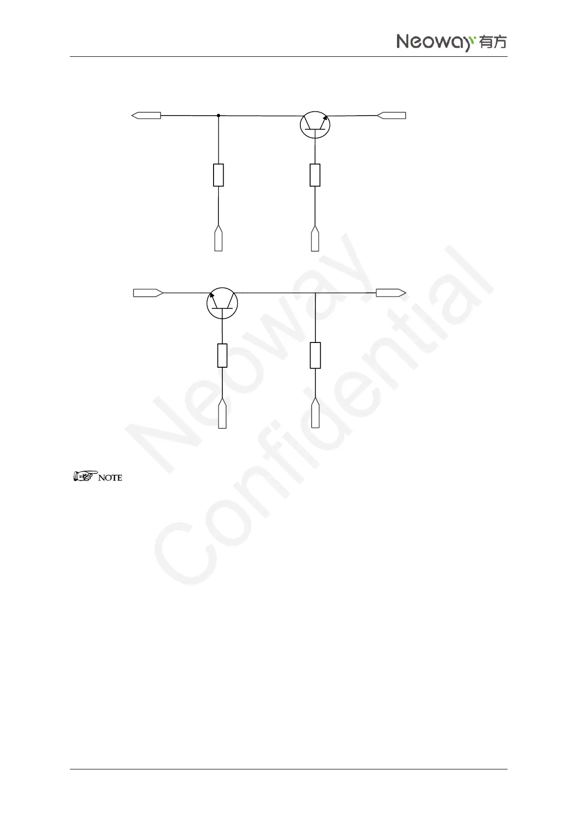
Figure 2-18 Recommended level shifting circuit 1
TXD
VDDIO_1P8
VCC_IO
4.7KΩ
10KΩ
Q1
R2
R3
MCU_URXD
MCU_UTXD
Q2
RXD
10KΩ
R1
4.7KΩ
R4
VDDIO_1P8
VDDIO_1P8
Components:
R2/R4: 2K-10K. The greater the UART baud rate is, the lower the R2/R4 values are.
R1/R3: 4.7K-10K The greater the UART baud rate is, the lower the R/R3R3 value is.
Q1/Q2: MMBT3904 or MMBT2222. High-speed transistor is better.
MCU_UTXD and MCU_URXD are respectively the TX and RX ports of the MCU while TXD and RXD
are respectively the TX and RX ports of the module.
Voltage at VCC_IO is the voltage at the UART of the MCU while voltage at VDDIO_1V8 is the voltage
at the UART of the module.
Figure 2-19 shows another recommended level shifting circuit.