N720 Hardware User Guide
Copyright © Neoway Technology Co., Ltd 22
2.5 UIM Card Interface
Compatible with 1.8 V/3 V UIM card
A 10 kΩ resistor is required between
VUIM and UIM-DATA.
A pull-up resistor is recommended
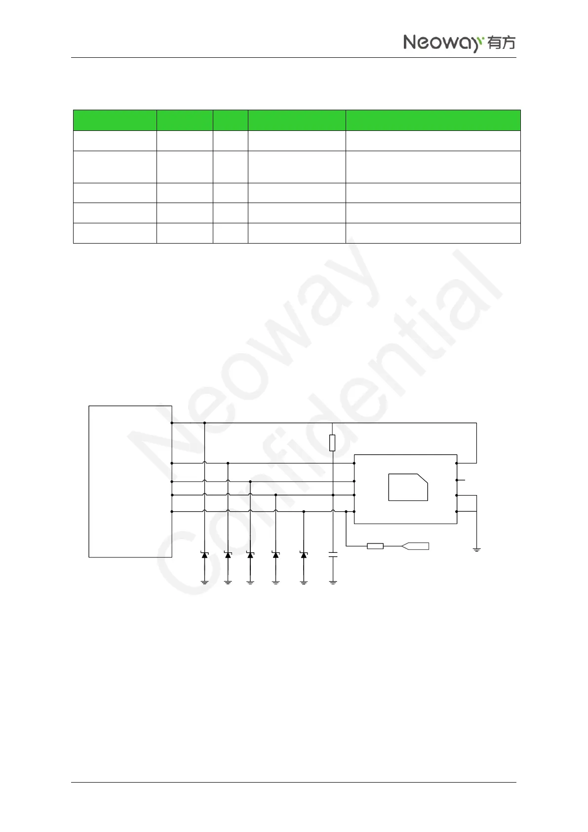
N720 supports 1.8 V/3 V UIM cards. VUIM is the power supply pin of the UIM card and its maximum
load is 30 mA. The UIM_DATA pin is not pulled up internally, so reserve a pull-up resistor externally in
design. UIM_CLK is the clock signal pin, supporting 3.25 GHz of clock frequency. Figure 2-15 shows the
reference design of the UIM card interface.
Figure 2-15 Reference design of SIM card interface
1 uF
UIM_DATA
UIM_CLK
UIM_RST
VUIM
N720
CLK
RST
VCC
VPP
GND
UIM card
DATA
GND
SIM-Det
UIM_DETECT
10KΩ
47KΩ
VDDIO_1P8
ESD protectors, such as ESD diodes or ESD varistors (with a junction capacitance of less than 33 pF), are
recommended to be added on the SIM signals, especially in automotive or other applications with bad
ESD. Replace the ESD diodes with 27 pF to 33 pF capacitors connecting to GND in common applications.
The ESD diodes or small capacitors should be close to UIM card.
N720 supports SIM card detection. UIM_DETECT is 1.8 V interrupt pins. Low level means UIM card
detected while high level mean no UIM card detected.