N720 Hardware User Guide
Copyright © Neoway Technology Co., Ltd 21
2.4 USB Interface
3.3 V to 5.2 V, typically 5 V
USB2.0, used for firmware download and
data transmission
Leave this pin unconnected if it is not used.
USB can be used to download firmware for N720 and establish data communication for commissioning.
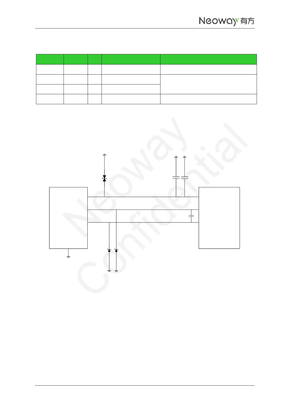
If the module is used only as USB device, the recommended USB circuit to use is shown in Figure 2-14.
Figure 2-14 USB circuit
USB_VBUS
USB_DM
USB_DP
USB_ID
GND
USB_ID
USB_DP
USB_DM
USB_VBUS
D1
C1
C2
D2 D3
DNI-18P
USB
connector
N720
Connect a 1 μF and a 22 pF filter capacitors in parallel to the VBUS pin and place them as close to the pin
as possible. TVS diodes are required for the VBUS power line. The junction capacitance of the TVS
protection diodes for USB_DP and USB_DM should be lower than 12 pF as possible. USB data lines
adopt differential trace design, in which the differential impedance is limited to 90 Ω characteristics
impedance. Isolate the traces from other signal traces.