N720 Hardware User Guide
Copyright © Neoway Technology Co., Ltd 17
Line Rules
The width of primary loop lines for VBAT on PCB must be able to support the safe transmission of 2 A
current and ensure no obvious loop voltage decrease. Therefore, the loop line width of VBAT is required
2 mm and the ground should be as complete as possible.
Separation
The module works in burst mode that generates voltage drops on power supply. Furthermore, this results
in a 217 Hz TDD noise through power (One of the way generating noise. Another way is through RF
radiation). Analog parts, especially the audio circuits, are subjected to this noise, known as a "buzz noise"
in GSM systems. To prevent other parts from being affected, it is better to use separated power supplies.
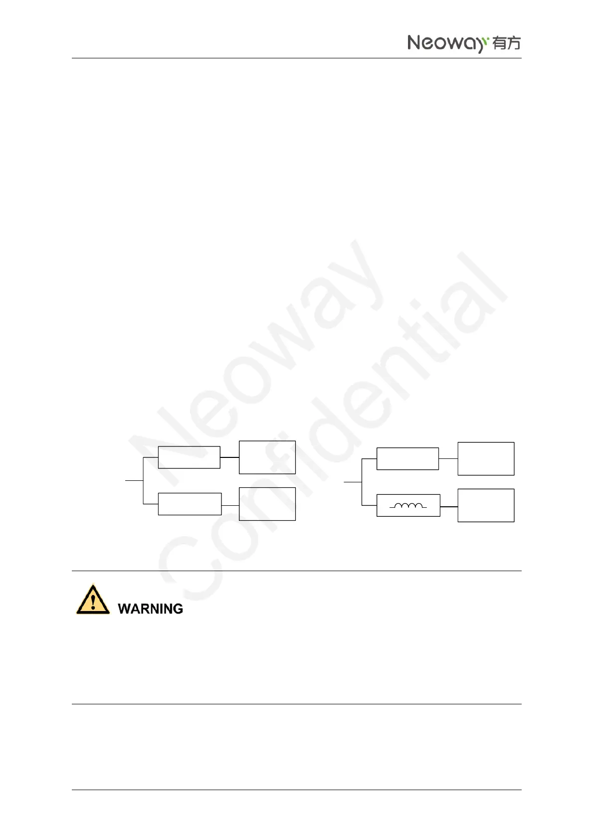
The module shall be supplied by an independent power, like a DC/DC or LDO. See Figure 2-6.
DC/DC or LDO should output rated peak current larger than 2 A.
The inductor used in Reference Design (b), should be a power inductor and have a very low resistance.
The value of 10 μH, with average current ability greater than 1.2A and low DC resistance, is
recommended.
Figure 2-6 Reference designs of separated power supply
Other circuitDC-DC/LDO
N720DC-DC/LDO
Power
Input
Other circuitDC-DC/LDO
N720
Power
Input
10 uH
Reference design (a) Reference design (b)
Never use a diode to make the drop voltage between a higher input and module power. Otherwise,
Neoway will not provide warranty for product issues caused by this. In this situation, the diode will
obviously decrease the module performances, or result in unexpected restarts, due to the forward voltage
of diode will vary greatly in different temperature and current.