Home
Neptune Technology
Media Converter
ProCoder R900i
Page 32 (Initializing the Data Logger)
Neptune Technology ProCoder R900i - Initializing the Data Logger
54 pages
Manual
Save Page as PDF
To Next Page
To Next Page
To Previous Page
To Previous Page
Loading...
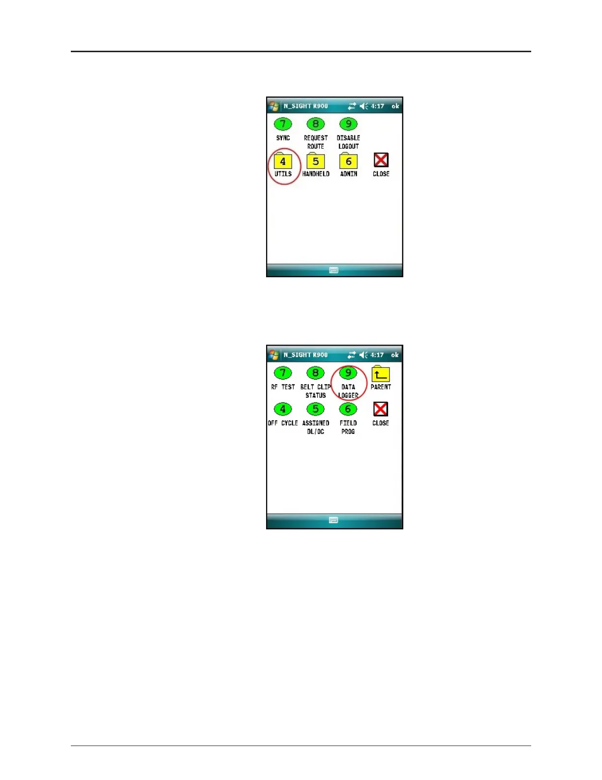
2
.
F
rom
t
he
HH
U
M
enu
sc
ree
n
,
clic
k
U
TILS
(o
ption
4
)
.
Fig
ure
1
5
–
N
_S
IGH
T
™
M
enu
3
.
Click
D
ATALO
G
GER
(
op
t
io
n
9
)
.
Fig
ure
1
6
–
Dat
a
L
ogg
e
r
Opt
ion
2
0
ProC
oder™)
R9
0
0
i
™
Inst
allat
ion
and
M
ainte
n
ance
G
uide
Chapt
er
5
:
Da
t
a
L
oggin
g
Ext
rac
tion
31
33
Table of Contents
Main Page
Default Chapter
7
Table of Contents
7
Chapter 1: Product Description
13
Overview
13
Procoder™)R900I™ Programming
14
Figure 1 - Procoder™)R900I
14
Chapter 2: Specifications
15
Electrical Specifications
15
Transmitter Specifications
15
Environmental Conditions
15
Functional Specifications
15
Table 1 - Transmitter Specifications
15
Table 2 - Environmental Conditions
15
Table 3 - Functional Specifications
15
Dimensions and Weight
16
Procoder™)R900I™ Dimensions
16
Figure 2 - Procoder™)R900I™ Dimensions
16
Table 4 - Dimensions and Weight
16
Figure 3 - Procoder™)R900I™ Antenna Dimensions
17
Chapter 3: Reading the Procoder™)R900I
19
How to Read
19
Figure 4 - Procoder™ Face and Sweep Hand
19
Common Causes of Leaks
20
Table 5 - Possible Leaks
20
How to Tell if Water Is in Use
21
If Continuous Leak Is Repaired
21
If Intermittent Leak Is Repaired
21
Chapter 4: Installing the Procoder™)R900I
23
Prior to Installation
23
Storage
23
Unpacking
23
Figure 5 - Procoder™)R900I™ Installation
23
Site Selection
24
Installing the Procoder™)R900I
24
New Meter Installation
24
Retrofit Meter Installation
25
Connecting the Procoder™)R900I ™ Through-The-Lid Antenna
26
Installing the Antenna
26
Figure 6 - Procoder™)R900I™ Antenna
26
Figure 7 - Through-The-Lid Antenna
26
Figure 8 - Locking the Nut on the Antenna
27
Figure 9 - Securing the Locking Nut
27
Figure 10 - Installation Complete
27
Attaching the Antenna to the MIU
28
Figure 11 - Removing the Dust Cover
28
Figure 12 - Aligning the F Connector
28
Figure 13 - Connecting the Coaxial Cable
29
Chapter 5: Data Logging Extraction
31
About Data Logging
31
Accessing Data Logging
31
Figure 14 - HHU Home Screen
31
Figure 15 - N_SIGHT™ Menu
32
Figure 16 - Data Logger Option
32
Initializing the Data Logger
33
Figure 17 - Reader ID Input
33
Figure 18 - HHU Time Confirmation
33
Figure 19 - Initializing RF Device
34
Figure 20 - Entering MIU ID
34
Figure 21 - Capture Button
35
Figure 22 - Meter Size Selection
35
Initiating RF-Activated Data Logging
36
Figure 23 - Start Button
36
Figure 24 - Listening for Data
36
Figure 25 - Receiving Data
37
Figure 26 - Graph Button
37
Sample Data Logging Graphs
38
Figure 27 - Examples of Data Logging Graphs
38
Table 6 - Data Logging Graph Legend
38
Off-Cycle Data Extraction
39
Figure 28 - HHU Home Screen
39
Belt Clip Transceiver
40
Chapter 6: Troubleshooting
41
Possible Reading Values
41
Table 7 - Reading Value Examples
41
Chapter 7: Contact Information
43
By Phone
43
By Fax
43
By Email
43
Appendix A: Procoder™)R900I™ Flags
45
Description of Flags
45
Table 8 - Eighth-Digit Resolution by Meter Size
45
Table 9 - Backflow Flag
45
Zero Consumption Flag
46
Table 10 - Leak Status Flag
46
Glossary
47
Index
51