MIU Wire Color / Encoder Terminal MIU Type
Black / B Green / G Red / R
l R900
®
l R450™
Black / G Green / R Red / B Sensus
Black /B White / G Red / R Itron
Black / G White / R Red / B Aclara
Black / G Green/ B Red / R Elster
Black / G Green / R Red /B Badger
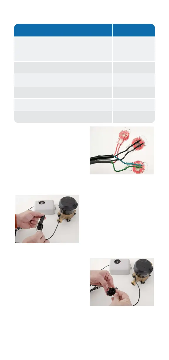
Table 1: Color Code for Wires
7. After you connect all
three colored wires, read
the encoder register to
ensure proper
connections, and that
the receptacle / MIU is
functioning properly.
Figure 13: Three Color
Wires Connected
Figure 14: Splice Tube
8. Take all three
connected
Scotchloks and push
them into the splice
tube until fully
covered by the
silicone grease.
9. Separate the gray wires,
and place them into the
slots on each side of the
splice tube.
Figure 15: Gray Wires
in Slot
- 9 -