
T
thomas85Jul 28, 2025
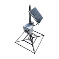
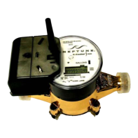
What to do if Neptune Data Loggers indicates an out-of-range reading?
- DDeanna RussellJul 28, 2025
If your Neptune Data Logger shows an out-of-range reading (greater than 99999999) or a diagnostic code from the MIU, it suggests that no meter reading history is available. To resolve this, swipe the MIU with a magnet to force it to read the register.