6
Ness Guardpost Installation & Programming
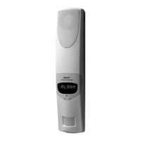
SGIII TWV Wiring
Applicable to SecurityGuard III / Guardpost Two Way Voice models
8 Ohm Horn Speaker
max. 1
12V Internal Screamer
max. 1
12V Strobe Light
max. 2 (2A total)
Blue
White
J3
1Tamper+
0V
AUX –
Ext Siren –
SIR+/AUX+/STR+
Strobe –
2
3
4
5
6
Black
Yellow
3k3 resistor
End of Line resistor and Normally Closed
tamper switch inside siren cover
Red
Red
Red
Green
COPYRIGHT NOTICE
All rights reserved. No part of this publication may be reproduced, transmitted or stored in a retrieval
system in any form or by any means, electronic, mechanical, photocopying, recording, or otherwise,
without the prior written permission of Ness.
Ness reserves the right to make changes to features and specications at any time without prior notica-
tion in the interest of ongoing product development and improvement.
© 2011 Ness Corporation ABN 28 069 984 372
Wire loom exits at rear of
the Guardpost housing
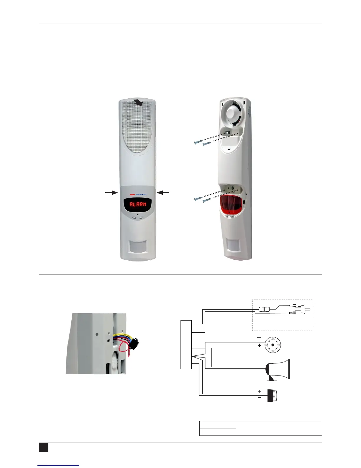
The front cover forms a secure clamshell when Guardpost is installed. The unit must be removed from
the wall before attempting to remove the front cover.
Screw mounting holes are provided for either at wall mounting or corner mounting.
Guardpost should be mounted in a position which provides a clear eld of view for the onboard PIR.
Wiring diagram for connecting optional external sirens and strobe.
Pull forward at the top
to remove the speaker
grille.
Pull sides to remove the
display cover.
INSTALLATION
WIRING
FLYING LEADS
Red AC
Optional External 17VAC power input
and solar power input
Red AC
Mounting holes (4)
are located behind
the speaker grille and
display cover.