Table 1. LEDs of the 8-port PoE+ and PoE++ models (Continued)
DescriptionLED
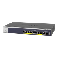
Port LEDs
Left LED, speed, activity, and link status:
Off. No link is established on the port.
Solid green. The port established a 1 Gbps link.
Blinking green. The port is transmitting or receiving packets at 1 Gbps.
Solid yellow. The port established a 10 or 100 Mbps link.
Blinking yellow. The port is transmitting or receiving packets at 10 or 100 Mbps.
LEDs 1 through 8
1GBASE-T RJ-45 port LEDs
(two LEDs per ports)
Right LED, PoE status:
Off. No PoE-powered device (PD) is connected to the port.
Solid blue. A PD is connected and the port is supplying power successfully.
Solid yellow. Indicates one of the following failures, which prevents the port
from supplying power:
•
A short circuit occurred on the PoE power circuit.
•
The PoE power demand exceeds the available power.
•
The PoE current exceeds the PD’s classification.
•
An out-of-proper-voltage band condition occurred.
Off. No link is established on the port.
Solid green. The port established a 1 Gbps link.
Blinking green. The port is transmitting or receiving packets at 1 Gbps.
Solid yellow. The port established a 10 or 100 Mbps link.
Blinking yellow. The port is transmitting or receiving packets at 10 or 100 Mbps.
LEDs 9 and 10
1GBASE-T RJ-45 port LED
(one LED per port)
Off. No SFP module link is established on the fiber port.
Solid green. The fiber port established a 1 Gbps link.
Blinking green. The fiber port is transmitting or receiving packets at 1 Gbps.
Solid yellow. The fiber port established a 100 Mbps link.
Blinking yellow. The fiber port is transmitting or receiving packets at 100 Mbps.
LEDs 11 and 12 for model
M4250-10G2F-PoE+
1GBASE-X SFP+ port LED
(one LED per port)
Off. No SFP+ module link is established on the fiber port.
Solid green. The fiber port established a 10 Gbps link.
Blinking green. The fiber port is transmitting or receiving packets at 10 Gbps.
Solid yellow. The fiber port established a 1 Gbps link.
Blinking yellow. The fiber port is transmitting or receiving packets at 1 Gbps.
LEDs 11 and 12 for models
M4250-10G2XF-PoE+ and
M4250-10G2XF-PoE++
10GBASE-X SFP+ port LED
(one LED per port)
Left LED, speed status:
Solid green. The port established a 1 Gbps link.
Solid yellow. The port established a 10 or 100 Mbps link.
Off. No link is established on the port.
OOB Ethernet port LEDs
(two LEDs per port, on the back
panel only)
Right LED, activity and link status:
Solid green. The port established a link.
Blinking green. The port is transmitting or receiving packets.
Off. No link is established on the port.
Hardware Installation Guide17Hardware Overview
AV Line of Fully Managed Switches M4250 Series
 Loading...
