S350 Series 24-Port (PoE+) and 48-Port Gigabit Ethernet Smart Managed Pro Switches
Get Started User Manual24
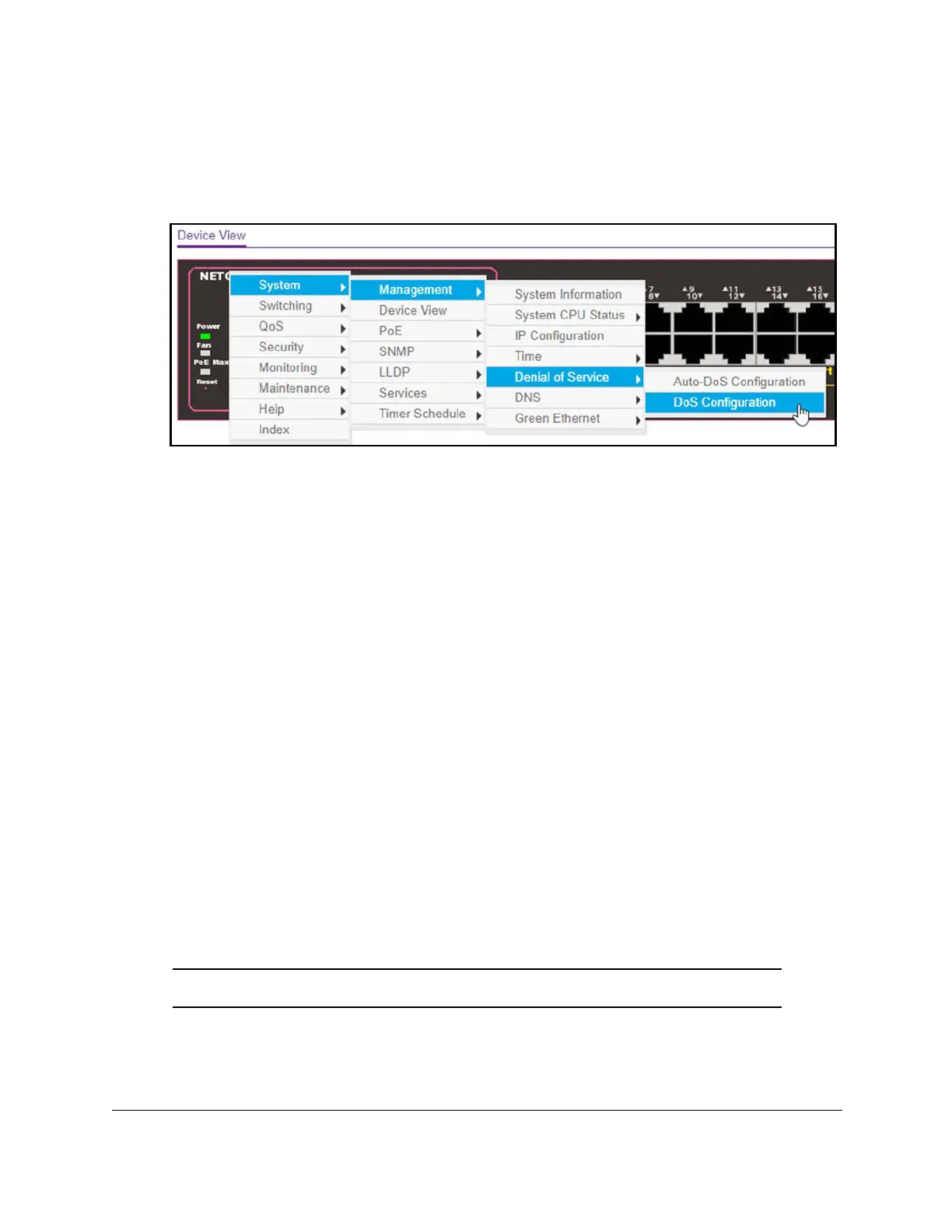
If you right-click the graphic, but do not right-click a specific port, the main menu displays.
This menu contains the same options as the navigation tabs at the top of the page.
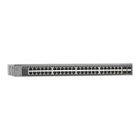
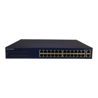
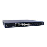
The following figure shows the details on the Device View page for model GS324TP.
Right-click the specific port that you want to view or configure to see a menu that displays
statistics and configuration options. Select the menu option to access the page that
contains the configuration or monitoring options.
The system LEDs are located on the left side of the front panel.
Power LED in the Device View
The Power LED is a bicolor LED that serves as an indicator of the power and diagnostic
status:
• Solid green. The switch is powered on and operating normally.
• Solid yellow. The switch is booting.
• Off. Power is not supplied to the switch.
Fan LED in the Device View (Models GS324TP and
GS348T)
The Fan LED serves as an indicator of the fan and diagnostic status:
• Off. The fan is operating normally.
• Solid yellow. A problem occurred with the fan.
Note: Model GS324T does not include a fan.

 Loading...