CONNECTION DIAGRAMS Page 19/112
4.2 Analogue GEOS12 TDController
GEO S12 TDController parameters have been optimized for 1 x RS15 (omni mode, mono) used in
conjunction with 2 x GEO S1210’s or 2 Geo x S1230’s (mono or stereo).
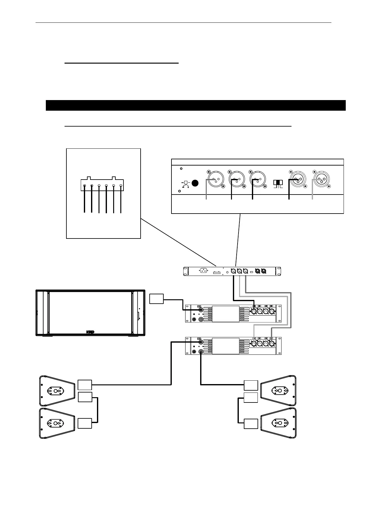
5 CONNECTION DIAGRAMS
5.1 GEO S12 & RS15 with GEOS12 TDController (Mono Omni Mode)
AMPLIFIER 1
AMPLIFIER 2
MONO
STEREO
Speakon 4
1 (+) / 1 (-) VLF1 *
2 (+) / 2 (-) VLF2 *
Speakon 4
Speakon 4
Speakon 4
Speakon 4
1 (+) / 1 (-) N.C.
2 (+) / 2 (-) FULL RANGE
Speakon 4
1 (+) / 1 (-) VLF
2 (+) / 2 (-) N.C.
TO AMPLIFIERS
B
ALANC
E
D IN
P
UT
S
RIGHT
LEFT
-
6dB
-
12dB
0dB
OUT
P
UT
L
E
V
E
L
B
ALANC
E
D OUT
P
UT
S
RIGHT LEFTSUB L+R
E
A
R
TH
LI
F
T
FROM AMPLIFIERS
+ 3-
+ 2 - + 1 -
S
E
N
S
E
IN
P
UT
(from amp terminals)
CAUTION
!
Sense must be connected for
speaker protection
SEE USER MANUAL
STEREO
IN
GEOS12
LEFT
GEOS12
RIGHT
SUB
OUT
GEOS12
LEFT
GEOS12
RIGHT
SUB
* VLF1 and VLF2 on one amplifier channel
 Loading...