CONFIGURABLE DIRECTIVITY DEVICE Page 29/112
7 CONFIGURABLE DIRECTIVITY DEVICE
The GEO Wavesource controls dispersion of acoustic energy using an hyperboloid acoustical reflector
in the “coupling plane” (the vertical plane of a curved vertical tangent array) and a diffraction slot in the
“non-coupling plane” (the horizontal plane of a curved vertical tangent array). The patented
Configurable Directivity Device consists of bolt-on flanges that alter the diffraction slot’s exit flare rate.
7.1 Installing & removing GEO’s Configurable Directivity flanges
GEO S12 are shipped in the 80° dispersion configuration;
120° flanges is an optional accessory.
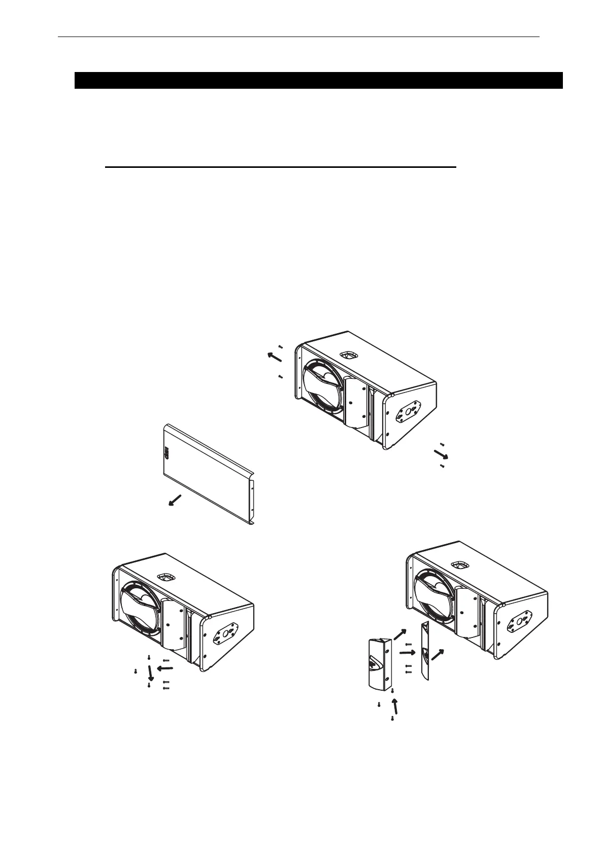
To change dispersion in the non-coupling plane to 120°:
• Remove the front grill (drawings below);
• Remove the three TORX (5x25) screws per flange on each side of the GEO Waveguide
(drawings below);
• Install the 120° flanges with the six TORX screws
• Re-install the grid, being careful that the NEXO logo must be on the 12” loudspeaker side.
REMOVING THE GRILL
REMOVING THE SCREWS REPLACING THE FLANGES
 Loading...