GEO S12 HARDWARE SETUP PROCEDURE Page 49/112
8.4.3 Single GEO S12 flown vertically
Required items
• 1 x Flying Bar for single vertical GEO S12 (GEOS12-TTC-V2)
• 1 x Lifting Ring (GEOS12-XHBRK)
• Or 1 x Truss hook (GEOS12-TCBRK-V2)
IMPORTANT
Ensure that truss suspension point is strong enough to hold GEO S12 weight.
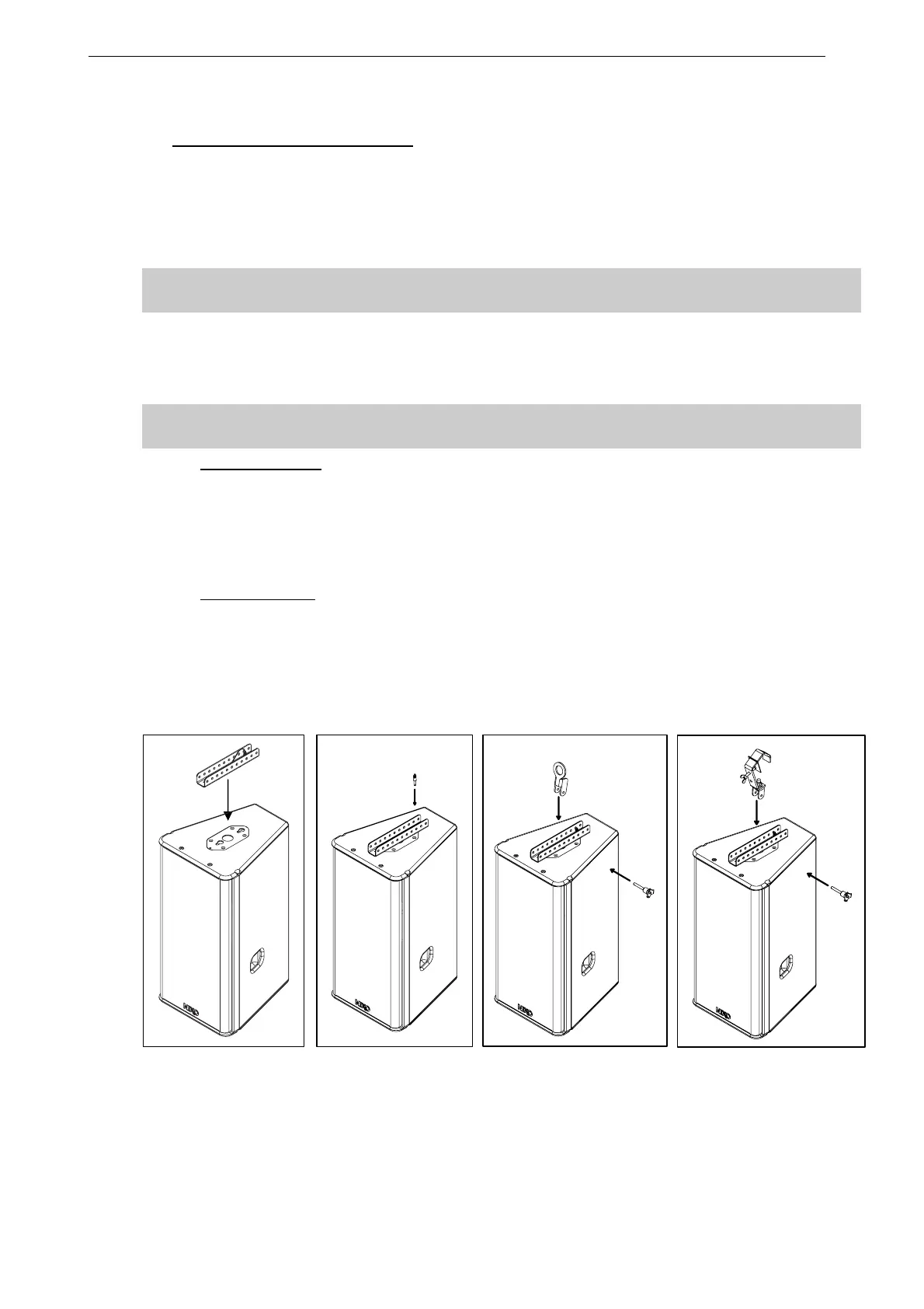
Procedure
• Slide flying bar GEOS12-TTC-V2 into GEO S12 connecting plate oblong holes;
• Lock safety pin into GEO S12 connecting plate;
IMPORTANT
Ensure that safety pin is properly locked into GEO S12 connecting panel.
Cable suspension:
• Connect lifting ring GEOS12-XHBRK to flying bar by inserting 8x45 quick release pin in required
holes for proper vertical aiming;
• Ensure lifting ring is properly locked to flying bar;
• Connect assembly to suspension point with sling and shackle (not provided).
Truss suspension
• Connect truss hook GEOS12-TCBRK-V2 to flying bar by inserting 8x45 quick release pin in
required holes for proper vertical aiming;
• Ensure truss hook is properly locked to flying bar;
• Lift and position assembly, lock hook on truss suspension point and secure with hook cable.
 Loading...

