PS SERIES HARDWARE SETUP PROCEDURE
System Manual PSR2 Series Page 45 / 109
6.3.7 LS18 and PS15R2 vertical array rigidly mounted on a ceiling
Required items
- 1 x GPI-BUMPER (allows +/-5° bumper tilt when installed below a flat surface; if higher bumper tilt is required, surface will
have to be defined accordingly)
- M x LSI-CPLA counter-plates for M x LS18
- 1 x GPI-ANPL3 for the PS15R2
- 4 x 12mm diameter screws (not provided)
IMPORTANT
Ensure that the ceiling is strong enough to hold 4 times LS18 and PS15R2 cluster weight and that the four
screws 12mm diameter and corresponding plugs required to fix the bumper under the ceiling are properly
dimensioned.
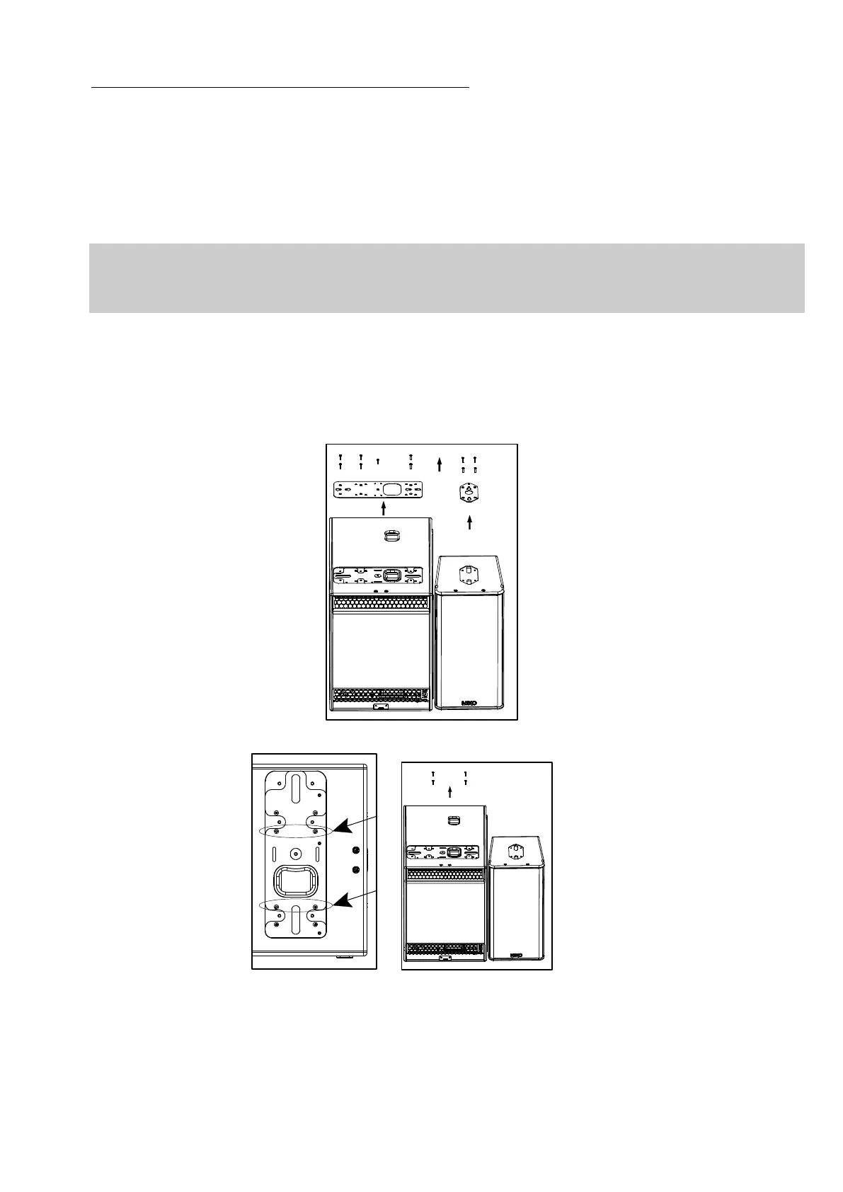
Procedure
- Set LS18s and PS15R2 sideways
- Remove the TORX screws holding connector plates on upper side of LS18 and PS15R2
- Remove the connector plates from LS18 and PS15R2
- Remove the 4 locking screws from LS18 side wood panel (see figure below), these are no longer to be used
- Apply Loctite 243 or equivalent to the screws that attach the LS18 connector plate to the cabinet, and reinstall the LS18
connector plates (see figure below left)
- Position PS15R2 bottom counter-plates (see figure below left)
- Position GPI-ANPL3 angle plate (set at 16°) and LSI-CPLA top counter-plates on LS18 upper sides according to figure
below right
- Use thread lock coated screws (if not apply Loctite 243 or equivalent to shoulder screws) from LSI-CPLA and GPI-ANPL
kits
 Loading...