ENGLISH – 23
9.1.4 FT210B photosensor
The FT210B photosensor combines in a single device a force
limiting system (type C, in accordance with the EN12453 stand-
ard) and a presence sensor that detects obstacles on the line
of sight between the TX transmitter and RX receiver (type D, in
accordance with the EN12453 standard). In the FT210B photo-
sensor, the signals regarding the status of the sensitive edge
are sent through the photocell range, integrating the 2 systems
in a single device. The transmitting element located on the mov-
ing leaf is battery-powered, which eliminates visually unpleasant
connection systems; special circuits reduce battery consump-
tion, ensuring up to 15 years’ life (see estimation details in the
product’s instructions).
A single FT210B device combined with a sensitive edge (TCB65,
for example) allows for attaining the level of safety of the “prima-
ry edge” required by the EN12453 standard for all “types of use”
and “types of activation”.
The FT210B photosensor combined with the “resistive” sensitive
edges (8.2 kΩ) is safe against faults (category 3 pursuant to the
EN 13849-1 standard). It is equipped with a special anti-colli-
sion circuit to prevent interference with other detectors, even
not synchronised, and allows for adding other photocells; for
example, in case of transit of heavy vehicles, where a second
photocell is normally positioned 1 m above the ground.
l
Consult the FT210B instruction manual for further
information on the connection and addressing
methods.
9.1.5 Gearmotor in SLAVE mode
The motor can function in SLAVE mode by suitably program-
ming and connecting it; this operating mode is used to automate
two opposite leaves that must move in a synchronised manner.
In this mode, a motor functions as MASTER, in other words, it
commands the manoeuvres, while the second motor functions
as SLAVE, executing the commands sent by the MASTER (all
the motors are MASTER by default).
The connection between MASTER and SLAVE is made via Blue-
BUS.
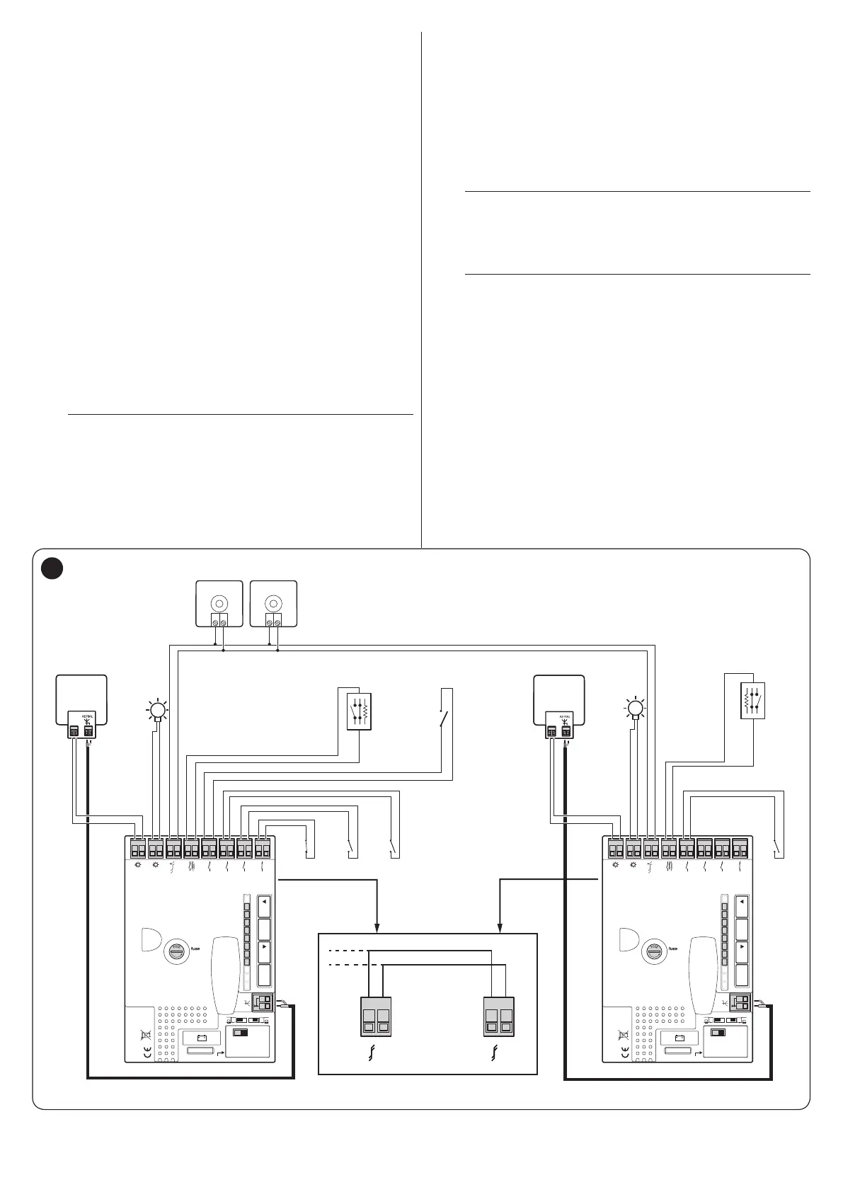
m
In this case, the polarity of the connections between
the two motors must be observed, as illustrated in
“Figure 36” (the other devices will continue not hav-
ing polarity).
l
It is not important which motor functions as MAS-
TER or SLAVE; the choice must take into account
the ease of the connections and the fact that the
“Step-by-Step” command of the SLAVE device al-
lows the full opening of the SLAVE leaf only.
Perform the following operations to install two motors in MASTER
and SLAVE mode:
1. install the two motors
2. connect the two motors as shown in “Figure 36”
Receiver
1.6AT
Flash
Bluebus
Stop
Sbs
Open
Aerial
Close
Aux In
L1L2L3L4L5L6L7L8
OpenStop/SetClose
OGI
FLASH
CLOSE
OPEN
AUX IN
NO NO
NC
Receiver
1.6AT
Flash
Bluebus
Stop
Sbs
Open
Aerial
Close
Aux In
L1L2L3L4L5L6L7L8
OpenStop/SetClose
OGI
FLASH
24V 4W
OGI
24V 4W
OGI
NO
TX
1 2
RX
1 2
NO
NC
8K2
Bluebus
MASTER
Bluebus
SLAVE
Bluebus
Bluebus
21 21
MASTER Board SLAVE Board
STOP
NO
NC
8K2
SBS
NO
IBT4N
IBT4N
36