6 – ENGLISH
3.4 PRE-INSTALLATION WORKS
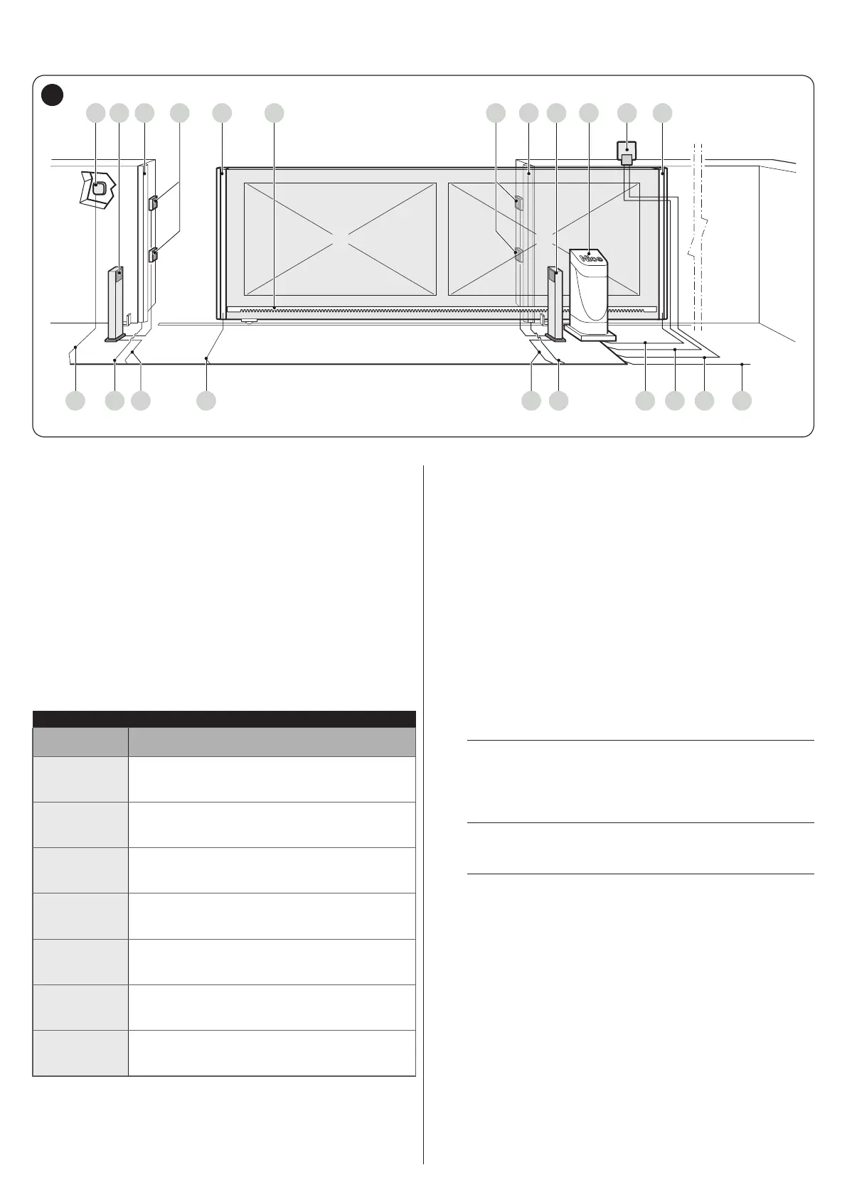
The gure shows an example of an automation system, constructed using Nice components.
A C E F G JD C H
1234546 657
BB I
4
A Key selector
B Photocells on column
C Main xed edge (optional)
D Photocells
E Main movable edge
F Rack
G Secondary xed edge (optional)
H SLH400
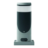
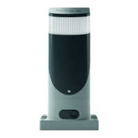
I Warning light with incorporated antenna
J Secondary movable edge (optional)
These above-mentioned components are positioned according
to a typical standard layout. Using the layout in “Figure 4” as a
reference, dene the approximate position in which each com-
ponent of the system will be installed.
Table 4
TECHNICAL SPECIFICATIONS OF ELECTRICAL CABLES
Identication
no.
Cable characteristics
1
GEARMOTOR POWER SUPPLY cable
1 cable 3 x 1.5 mm
2
Maximum length 30 m [note 1]
2
WARNING LIGHT cable
1 cable 2 x 0.5 mm
2
Maximum length 20 m
3
ANTENNA cable
1 x RG58-type shielded cable
Maximum length 20 m; recommended < 5 m
4
MOVABLE EDGES cable
1 cable 2 x 0.5 mm
2
[note 4]
Maximum length 30 m [note 5]
5
FIXED EDGES cable
1 cable 2 x 0.5 mm
2
[note 4]
Maximum length 30 m
6
PHOTOCELL cable
1 cable 2 x 1.5 mm
2
Maximum length 30 m [note 2]
7
KEY SELECTOR cable
2 cables 2 x 0.5 mm
2
[note 3]
Maximum length 50 m
Note 1 If the power supply cable is longer than 30 m, a cable
with larger cross-sectional area (3 x 2.5 mm
2
) must be
used and a safety earthing system must be installed
near the automation.
Note 2 If the BlueBus cable is longer then 30 m, up to maxi-
mum 50 m, it is necessary to use a cable with a greater
cross-sectional area (2 x 1 mm
2
).
Note 3 These two cables can be replaced by a single 4 x 0.5
mm
2
cable.
Note 4 If more than one edge is present, refer to the “STOP in-
put” paragraph for the type of connection recommend-
ed.
Note 5 Movable edges must be connected to sliding leaves us-
ing special devices, which enable the connection even
when the leaf is moving.
a
Before proceeding with the installation, prepare the
required electrical cables by referring to “Figure 4”
and to that stated in the “TECHNICAL SPECIFICA-
TIONS“ chapter.
a
The cables used must be suited to the type of envi-
ronment of the installation site.
a
When laying the pipes for routing the electrical ca-
bles, take into account that any water deposits in
the junction boxes may cause the connection pipes
to form condensate inside the control unit, thus
damaging the electronic circuits.