ENGLISH – 9
3.6 ADJUSTING THE MECHANICAL LIMIT
SWITCHES
To adjust the limit switches, proceed as follows:
1. unlock the gearmotor with the relevant key provided (refer
to the “Manually unlocking and locking the gearmotor”
paragraph)
2. manually perform a complete opening and closing ma-
noeuvre to allow the mechanical limit switches to self-ad-
just.
m
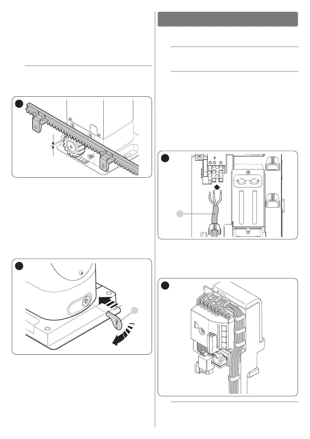
During this manoeuvre, check that the rack moves
aligned with the pinion, with a maximum misalign-
ment of 5 mm, and that there is a 1–2 mm clearance
between pinion and rack along its entire length.
1÷2 mm
13
3. lastly, manually position the leaf halfway along its path
and lock the gearmotor using the relevant key (refer to
the “Manually unlocking and locking the gearmotor”
paragraph).
3.7 MANUALLY UNLOCKING AND LOCKING THE
GEARMOTOR
The gearmotor is equipped with a mechanical unlocking device
that can be used to open and close the gate manually.
These manual operations should only be performed in case of
a power outage, malfunctions or during the installation phases.
To unlock the device:
4. insert the key (A) and turn it clockwise by 90°
A
14
5. the gate leaf can now be moved manually to the desired
position.
To lock the motor:
1. turn the key (A) anti-clockwise by 90°
2. remove the key.
ELECTRICAL CONNECTIONS
4
4 ELECTRICAL CONNECTIONS
4.1 PRELIMINARY CHECKS
f
All electrical connections must be made with the
system disconnected from the mains electricity and
with the back-up battery (if present) disconnected.
a
The connection operations must only be carried out
by qualied personnel.
To make the electrical connections:
1. insert all the connecting cables into the various devices,
leaving them 20–30 cm longer than necessary. Refer to “
Table 4” for the type of cables and to “Figure 4” for the
connections.
2. use a clamp to hold together all the cables entering the
gearmotor then place the clamp slightly below the cable
entry hole
3. connect the power cable (A) to the relevant terminal as
shown in the gure, then use another clamp to fasten the
cable onto the rst cable ring
A
15
4. connect the other cables according to the diagram shown
in “Figures 16” and 17. For greater convenience, the ter-
minals are removable.
5. after making the connections, lock the cables in the ap-
propriate rings. The excess part of the antenna cable
must be secured to the other cables.
16
l
To connect 2 motors on opposite leaves, refer to the
“Gearmotor in SLAVE mode” paragraph.