24 – ENGLISH
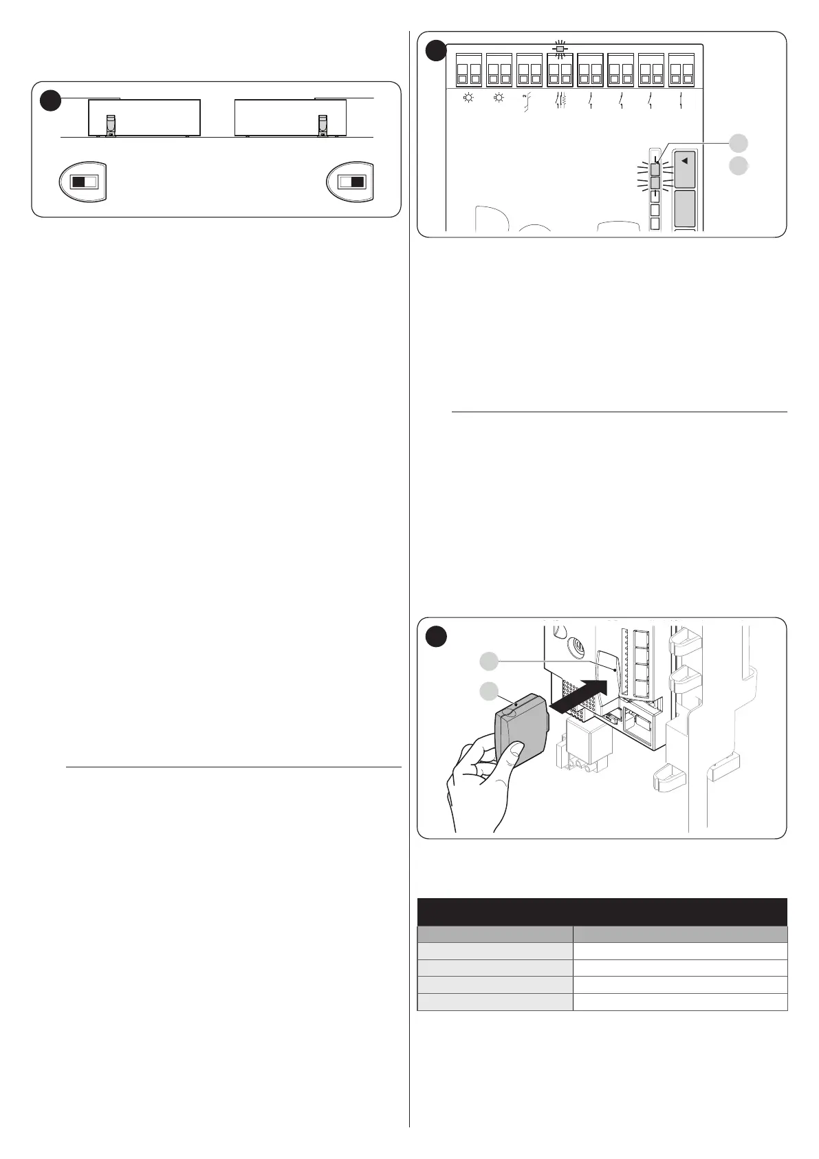
3. select the opening direction of the two motors, as shown
in the gure (also refer to the “Choosing the direction”
paragraph)
37
4. power the two motors
5. in the SLAVE motor, programme the “SLAVE mode” func-
tion (see “Table 6”)
6. perform the procedure for acquiring devices on the SLAVE
motor (see the “Device learning” paragraph)
7. perform the procedure for acquiring devices on the MAS-
TER motor (see the “Device learning” paragraph)
8. perform the procedure for acquiring the length of the
leaves on the MASTER motor (see the “Leaf length learn-
ing” paragraph).
In connecting the two motors in SLAVE-MASTER mode, verify
that:
– all devices must be connected to the MASTER motor (as
shown in “Figure 36”), including the radio receiver
– when using back-up batteries, each motor must have its own
battery
Once a motor has been congured as SLAVE, it nonetheless
maintains some functions (listed below) separate from the MAS-
TER motor.
Level 1 functions (ON-OFF functions)
– Stand-by
– Peak
– Slave mode
Level 2 functions (adjustable parameters)
– OGI output
– Motor force
– Error log
On the SLAVE motor it is possible to connect:
– an own warning light (Flash)
– an own Open Gate Indicator (OGI)
– an own sensitive edge (Stop)
– an own command device (Sbs) that controls the full opening
of the Slave leaf only.
– In the Slave, the Open, Close and Aux_In inputs are not used.
m
In the SLAVE, the “Open”, “Close” and “Aux_In” in-
puts are not used.
9.1.6 Learning of other devices
Normally the learning of devices connected to “BlueBUS” and
the “STOP” input takes place during the installation stage; how-
ever, if new devices are added or old ones removed, the learn-
ing process can be redone.
Flash
Bluebus
Stop
Sbs
Open
Close
Aux In
L1L2L3L4L5
OpenStop/Set
OGI
L1
L2
38
To do this:
1. simultaneously press and hold the [Open
p
] and [Stop/
Set] buttons
2. release the buttons when LEDs “L1” and “L2” start ash-
ing rapidly (after roughly 3 seconds)
3. wait a few seconds until the control unit has completed the
device learning phase
4. at the end of this phase, the “Stop” LED must be lit, LEDs
“L1” and “L2” must switch off, while LEDs “L1…L8” will
switch on depending on the status of the ON-OFF func-
tions they represent.
m
After having added or removed devices, the auto-
mation test must be carried out again as specied
in the “Testing” paragraph.
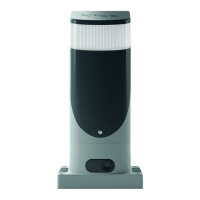
9.1.7 Connecting an SM-type radio receiver
The control unit has a slot for mounting radio receivers with SM
connector (optional accessories) belonging to the SMXI, OXI,
etc. families, which can be used to remotely control the control
unit through transmitters that intervene on the unit’s inputs.
To install a receiver (“Figure 39”):
1. insert the receiver (A) in the appropriate slot (B) on the
control unit’s electronic board.
B
A
39
The association between the radio receiver output and the com-
mand executed by the motor is shown in “Table 14”:
Table 14
SMXI / SMXIS OR OXI / OXIFM / OXIT / OXITFM IN MODE 1 OR MODE
2
Receiver output Command
Output No. 1
“Step-by-Step”
Output No. 2
“Partial opening”
Output No. 3
“Open”
Output No. 4
“Close”