28 – ENGLISH
TECHNICAL SPECIFICATIONS
12
12 TECHNICAL SPECIFICATIONS
l
All technical specications stated in this section refer to an ambient temperature of 20°C (± 5°C). Nice S.p.A.
reserves the right to apply modications to the product at any time when deemed necessary, without altering
its functions and intended use.
Table 16
TECHNICAL SPECIFICATIONS
Description Technical specication
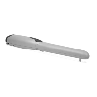
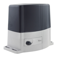
Product type
Electro-mechanical gearmotor for the automatic movement of sliding gates for residential
use, inclusive of electronic control unit
Pinion
Z: 15; Module: 4; Pitch: 12.6 mm; Primitive diameter: 60 mm
Peak torque [corresponding to the
ability to develop a force capable of
moving the leaf]
12 Nm; corresponding to the ability to move a leaf with dynamic friction of up to 400N
Nominal torque [corresponding to the
ability to develop a force capable of
keeping the leaf moving]
6 Nm; corresponding to the ability to keep a leaf moving with dynamic friction of up to 200N
Nominal torque speed
0,18 m/s
No-load speed (the control unit allow
for programming 6 speeds roughly
equal to: 100, 85, 70, 55, 45, 30%)
0,34 m/s
Maximum frequency of operating
cycles (at nominal torque)
35 cycles/hour (the control unit limits the cycles to the maximum specied in Tables “Table
2” and “Table 3”)
Maximum continuous operating time
(at nominal torque)
10 minutes
Application limits
In general, SLH400 is able to automate gates weighing up to 400 kg or up to 7 metres long,
according to the limits shown in “Table 1” and “Table 2”.
Durability
Estimated between 20,000 and 180,000 cycles, depending on the conditions shown in “
Table 3”
Power supply Slight 230VC (+10% -15%) 50/60Hz
Maximum absorbed power at peak
330W
Insulation class
1 (a safety earthing system is required)
Emergency power supply
With optional accessory PS124
Warning light output
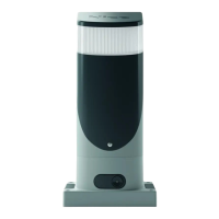
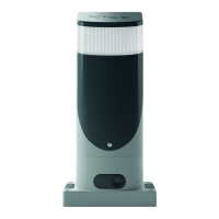
For 2 ELDC LED warning lights or maximum 2 x 12 V 21 W lamps
OGI output
For one 24 V maximum 4 W lamp (the output voltage may vary between –30 and +50% and
can also control small relays)
BLUEBUS output
One output with maximum load of 15 BlueBus units
STOP input
For normally closed or normally open contacts or for 8.2 kΩ xed resistor contacts with self-
learning (any variation from the memorised status triggers the STOP command)
Sbs input
For normally open contacts (closing of the contact triggers the STEP-BY-STEP command)
OPEN input
For normally open contacts (closing of the contact triggers the “OPEN” command)
CLOSE input
For normally open contacts (closing of the contact triggers the CLOSE command)
AUX_IN input
For normally closed contacts (opening the contact triggers a STOP command)
Radio connector
SM connector for SMXI and SMXIS receivers
Radio ANTENNA input
52 Ω for RG58-type cable or similar
Programmable functions 8 ON-OFF functions and 8 adjustable functions (see “Table 6” and “Table 7”)
Self-learning functions
Self-learning of the devices connected to the BlueBus output
Self-learning of the type of “STOP” device (Normally Open, Normally Closed contact or 8.2
kΩ resistor)
Self-learning of the gate length and calculation of the deceleration and partial opening
points
Operating temperature
-20°C ÷ 55°C
Use in highly acid, saline or potentially
explosive atmosphere
No
Protection rating
IP 44 on the nished product if installed according to proper installation criteria
Dimensions and weight
131x135xh405; 6,5 kg