4 – ENGLISH
INSTALLATION
3
3 INSTALLATION
3.1 PRE-INSTALLATION CHECKS
a
The installation must be carried out by qualied
personnel in compliance with the current legisla-
tion, standards and regulations, and with the in-
structions provided in this manual.
Before proceeding with the product’s installation, it is necessary
to:
– check the integrity of the supply
– check that all the materials are in good working order and
suited to the intended use
– make sure that the structure of the gate is suitable for being
automated
– make sure that the weight and dimensions of the gate leaf
fall within the operating limits specied in the “Product usage
limits” paragraph
– check that the force required to start moving the gate leaf is
less than half the “maximum torque”, and that the force re-
quired to keep the gate leaf moving is less than half the “nomi-
nal torque”; compare the resulting values with those specied
in the “TECHNICAL SPECIFICATIONS” chapter. The manu-
facturer recommends a 50% margin on the force, as unfavour-
able climatic conditions may cause increased friction.
– verify that there are no points of greater friction during the
opening and closing movements along the entire gate path
– verify that there is no risk of derailment of the leaf or that it may
come off the guides
– verify that the overrun mechanical stops are sturdy enough
and that they do not deform even if the leaf should strike them
forcefully
– verify that the gate leaf is well balanced: it must not move by
itself when left in any position
– make sure that the installation area is not subject to ooding; if
necessary, the product must be installed appropriately raised
above ground level
– verify that the area where the gearmotor is installed allows for
unlocking the latter and manoeuvring easily and safely
– verify that the mounting positions of the various devices are
protected against impacts and that the mounting surfaces are
sufciently sturdy
– prevent any parts of the automation from being immersed in
water or other liquids
– keep the product away from heat sources and open ames
and acid, saline or potentially explosive atmospheres; these
may damage the product and cause malfunctions or danger-
ous situations
– if there is an access door in the gate, or within its range of
movement, make sure that it does not obstruct the gate’s nor-
mal path; install an appropriate interlock system if necessary
– connect the control unit to an electricity supply line equipped
with a safety earthing system
– connect the gate to the earthing device in accordance with
the current legislation
– include a device on the electric power line ensuring complete
disconnection of the automation from the grid. The disconnec-
tion device must have contacts with a sufcient gap to ensure
complete disconnection, under the Category III overvoltage
conditions, in accordance with the installation instructions.
Should it be necessary, this device guarantees fast and safe
disconnection from the power supply; it must therefore be po-
sitioned in view of the automation. If placed in a non-visible
location, it must have a system that blocks any accidental on
unauthorised reconnection of the power supply, in order to
prevent dangerous situations. The disconnection device is not
supplied with the product.
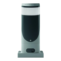
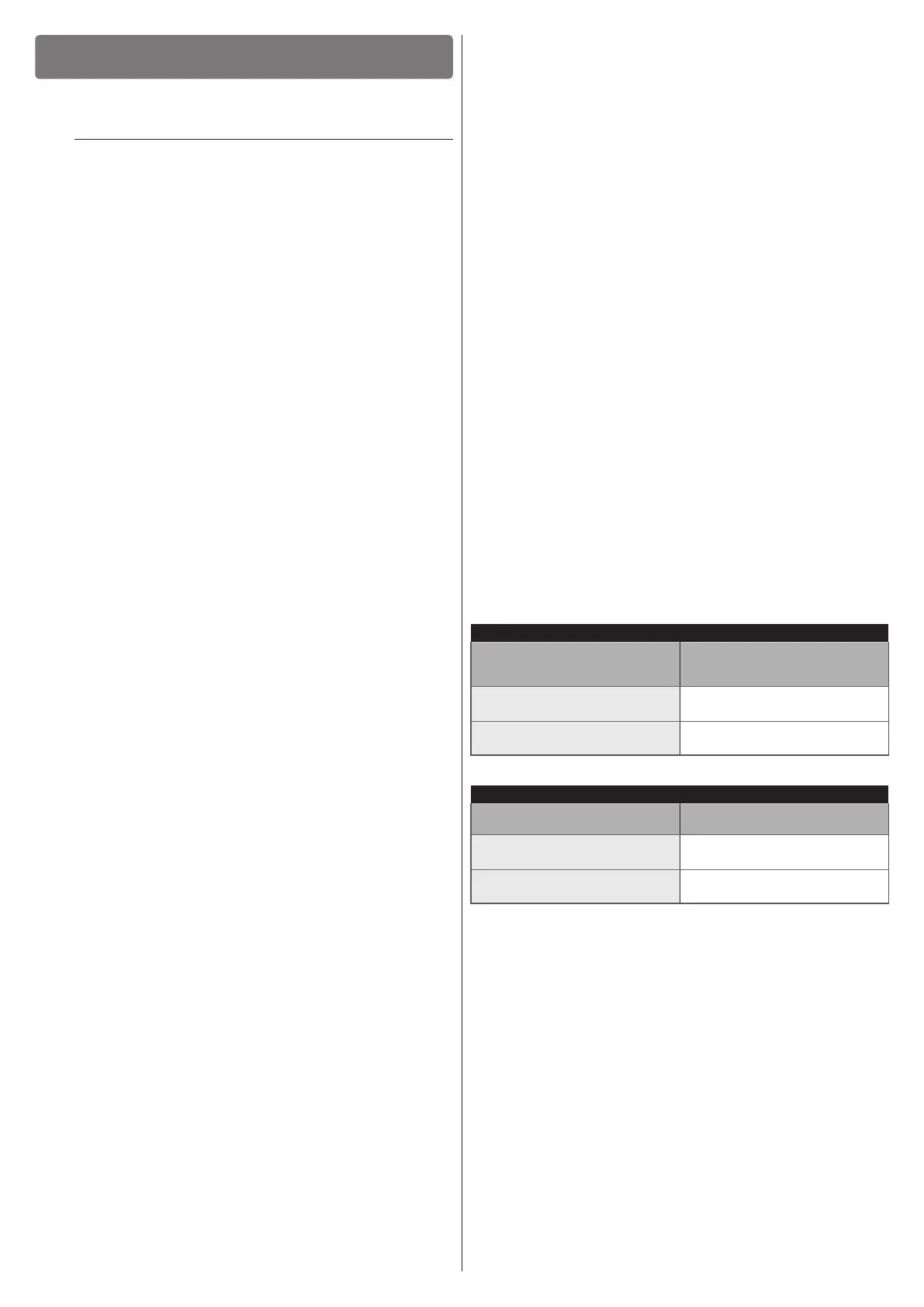
3.2 PRODUCT USAGE LIMITS
The data relative to the product’s performances is included in
the “TECHNICAL SPECIFICATIONS” chapter and is the only
data that allows for properly assessing whether the product is
suitable for its intended use.
The structural characteristics of the product make it suitable for
use on sliding gates, according to the limits indicated in the fol-
lowing tables.
The actual suitability of the product to automate a specic slid-
ing gate depends on friction and on other factors, even occa-
sional, such as the presence of frost, which may interfere with
the gate leaf’s movement.
For an effective check, it is essential to measure the force nec-
essary to move the gate leaf along its entire path and ensure
that this is less than half of the “nominal torque” indicated in
“TECHNICAL SPECIFICATIONS” chapter (a 50% margin on
the force is recommended, as unfavourable climatic conditions
may cause increased friction); furthermore, it is necessary to
take into account that shown in the following tables to dene the
number of cycles/hour, the consecutive cycles and maximum
speed allowed.
Table 1
SLH400 - LIMITS IN RELATION TO THE GATE LEAF LENGTH
Gate leaf length (m)
Maximum no. of cycles/hour
Maximum no. of consecutive
cycles
Up to 4
35
14
4 ÷ 6
23
11
Table 2
SLH400 - LIMITS IN RELATION TO THE GATE LEAF WEIGHT
Gate leaf weight (kg)
Percentage of cycles
Maximum speed allowed
Up to 200
100%
V6 = Extremely fast
200 ÷ 400
50%
V5 = Very fast
The length of the leaf is used to determine both the maximum
number of cycles per hour and the consecutive cycles, while
its weight is used to determine the cycle reduction percentage
and the maximum speed allowed; for example, if the leaf is 5 m
long it, we will have 23 cycles/hour and 11 consecutive cycles.
However, if the leaf weighs 350 kg, the cycles must be reduced
to 50%, resulting in 11 cycles/hour and 5 consecutive cycles,
while the maximum speed allowed is V5: “Very fast”. To prevent
overheating, the control unit has a manoeuvre limiter that works
based on the motor force and duration of the cycles, intervening
whenever the maximum limit is exceeded. The manoeuvre limit-
er also measures the ambient temperature and further reduces
the number of manoeuvres in case of particularly high temper-
atures.