42
4. Connections
Digitax SF Instruction Manual
5. Descriptions of CN1 Connector Signals
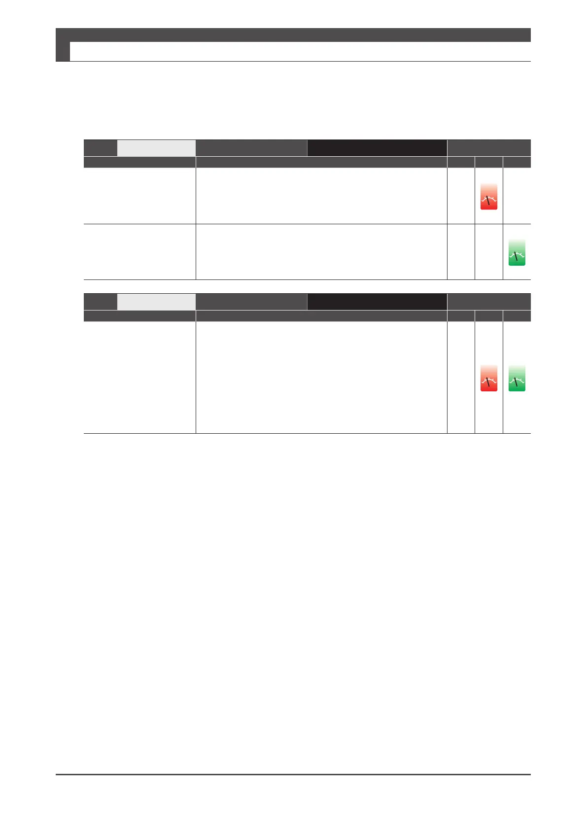
Pin No.
32
Interface Circuit
CA(page 48) Control Mode
Signal Description P S T
A_SPEED
Analog Velocity
Command
Speed command input with analog voltages (-10V to +10V). A_
GND (Pin No.33) is the reference point of electric potential.
ol
A_TRQ
Analog Torque
Command
Torque command input with analog voltages (-10V to +10V).
A_GND (Pin No.33) is the reference point of electric potential.
ol
Pin No.
33
Interface Circuit
CA(page 48) Control Mode
Signal Description P S T
A_GND
Analog Command
Ground
This is the reference point of electric potential for Analog
command voltage input to Pin No.32.
■ TIP
If the analog velocity command circuit of the host controller
is isolated from 24V control power supply, connect A_GND
to signal ground of the host controller, not to GND of control
power, If the analog velocity command circuit is not isolated,
connect A_GND to GND of control power.
ol
ol