NE200/300 Series Drive User Manual
174 Chapter 6 Parameter description
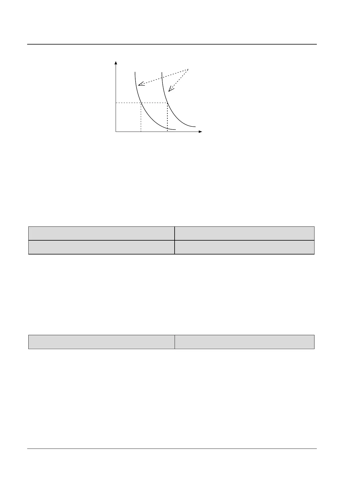
1 min
Time
Output current
100% 200%
50% 100%
Motor overload
protective
coefficient
Fig 6-27 Motor overload protection curve
Motor overload protection coefficient calculates:
Motor overload protection coefficient = (the max allowed current of load
÷ rated output current of drive) × 100%
Generally, the Max load current is the motor rated current.
FC.02 Pre-overload detection Level
Range: 30.0~200.0%【160.0%】
FC.03 Pre-Overload detection time Range: 0.0~80.0s【60.0s】
FC.02 defines the current threshold for overload pre-alarm protection.
The setting range is a percentage value of rated current.
FC.03 defines the time during which the drive current exceeds FC.02. If
the drive continuous output current lager than FC.02 for some time defined
in FC.03, the drive will output pre-alarm signal (OLP2).
FC.04 Current amplitude limit Range: 0~2【2】
During the Acc/Dec running, if the drive actual current exceeds the
“Current amplitude limiting level” (PC.04), the drive stops the Acc/Dec
process till the current is lower than the limit point.
In the drive’s constant speed operating process, if PC.04 is set to 2,
when the drive actual current exceeds “Current amplitude limiting level”
(PC.05), the drive will reduce output frequency till the current gets lower
than the limit point. Then the drive will accelerates to the previous constant