NE200/300 Series Drive User Manual
Chapter 3 Wiring of Drive 43
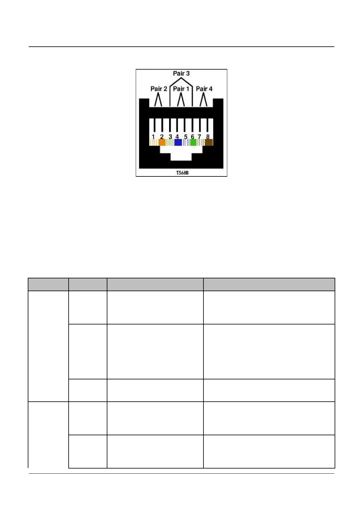
Fig.3-18 T568B standard
The cables connecting keypad and control board use standard RJ-45
Interface, namely both sides are connected according to EIA/TIA568B
standard. Users can make the cable by themselves or purchase general
internet cable from market as keypad cable.
3.7.2 NE300 Standard configuration of control circuit terminals
Type
Termina
Terminal function Technical specification
Digital
input
X1
~
X3
Multi-functional input
terminals 1
~
3
Optical-isolator input
Frequency range:
:
0
~
200Hz
Voltage range: 0
~
24V
X4
X5
Multi-functional input or
Single pulse input 4, 5
Multi-functional input
:
same as
X1
~
X3
Single Pulse input:
:
0.1Hz
~
50kHz
Voltage range
:
0
~
24V
COM
multi-functional input
terminals common end
Internal isolated with GND
Digital
output
24V 24V
24V±5%, Maximum load :200mA,
with overload and short circuit
protection
Y1 Open collector output 1
Optical-isolator output
maximum output current: 50mA
Output voltage range
:
0
~
24V