Electrical installation
Electrical connections
Safety
ATTENTION
All work must be carried out by qualified persons and in compliance with existing legislation and
regulations.
ATTENTION
It is important that power is disconnected when working with the unit's electrical components.
It is important to check that cables have not been damaged or trapped during connection and use.
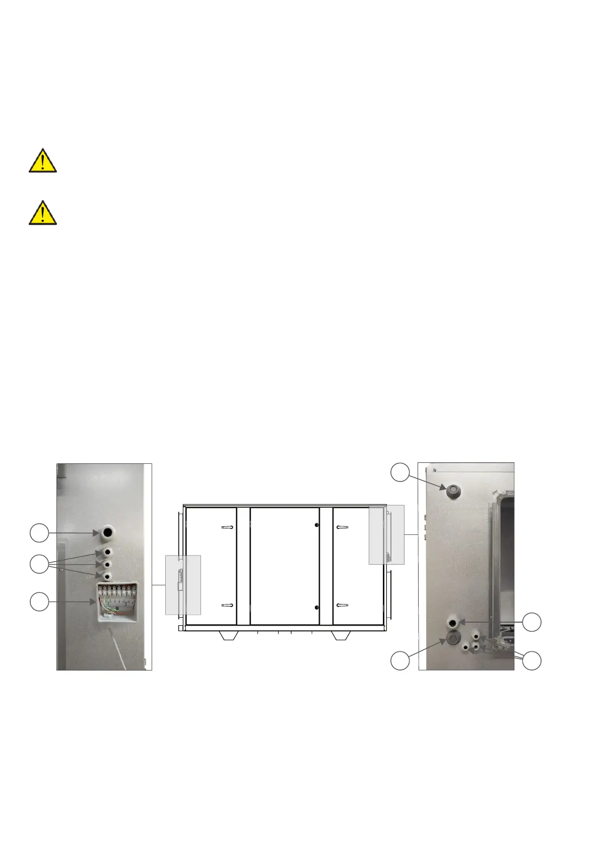
Connections overview
All electrical connections are located on the right and left sides of the system, respectively, next to the
duct connections.
1. Connection supply cable for VPM
2. Sockets for various electrical connections and external sensors
3. Connecting the control panel
4. Connecting the electrical after-heating element
A. Connecting water after-heating element - supply flow
B. Connecting water after-heating element - return flow
1
A
B
2
4
2
3
Illustration shown is for a right version
22
 Loading...