Electrical connection of the unit
Power supply
CAUTION
The power supply, including a safety switch, must be installed by an authorized electrician.
The unit is connected to 3x400V + N + J.
Reference is also made to the electrical diagram supplied with the system.
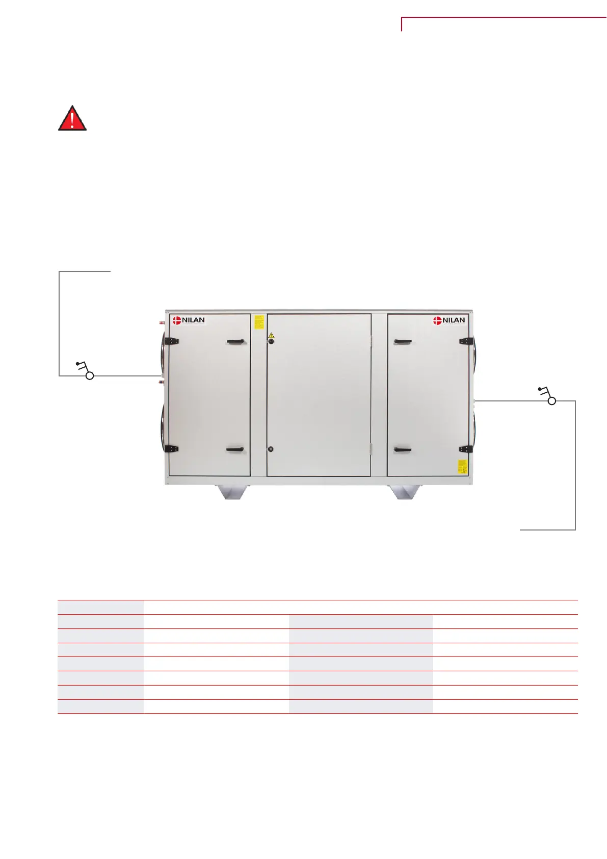
Unit
Illustration shown is for a left version
Power supply
3x400V 50HZ
Safety switch
Power supply for electric after-heating element (accessory)
3x400V 50HZ
Safety switch
Ampere consumption after equipping:
Unit Compressor* Fan (2 motors) total **
MTZ VTZ Max. power
[Amp] [Amp] [Amp] max.
VPM 120 5.0 - 5.60
VPM 240 8.0 7.4 6.20
VPM 360 9.5 12 5.60
VPM 480 15 12 7.80
VPM 560 18 16 7.80
* Depending on MTZ / VTZ compressor (configuration dependent).
** Ampere consumption on fan motors depending on air volume and pressure loss.
VPM 120-560 (English) BY NILAN
23
 Loading...