Left version:
8
1a
13b
13a
1b
3
6 5
2
11a 9
7
1d
1c
14
4
11b12
10 16
16
15
2
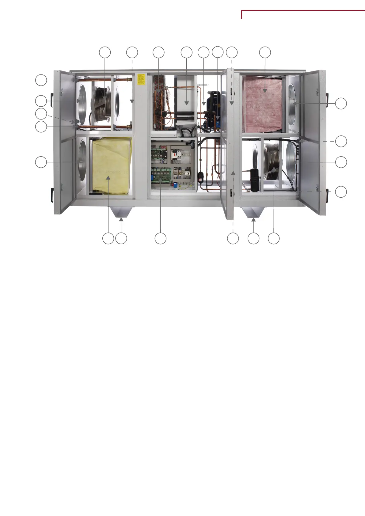
1. Duct connections
a. supply air
b. extract air
c. outdoor air
d. discharge air
2. Electrical connections (located on the side of the unit - in the picture they are behind the door)
3. Extract air filter (standard is ISO ePM10> 50%)
4. Outdoor air filter (ISO ePM10> 50% or ISO ePM1> 70%)
5. Valves for cooling manometer
6. Heatpipe / passive heat exchanger (behind shielding and automatic)
7. Condensate drainage (located on the side of the unit - in the picture it is behind the door)
8. Supply air fan
9. Extract air fan
10. Automatic (inside the electric cabinet)
11. Condensers and evaporators
a. Evaporator / Condenser
b. Condenser/Evaporator
12. After-heating element water / electricity (accessory)
13. Pipe for supply / return to water-heating element
a. Supply
b. Return
14. Compressor frequency converter - only with VTZ compressor (in the picture it is behind the door
and shielding)
15. Compressor
16. Base-feet
VPM 120-560 (English)
BY NILAN
9
 Loading...