95Service Manual – SC5000 20 - Drive System
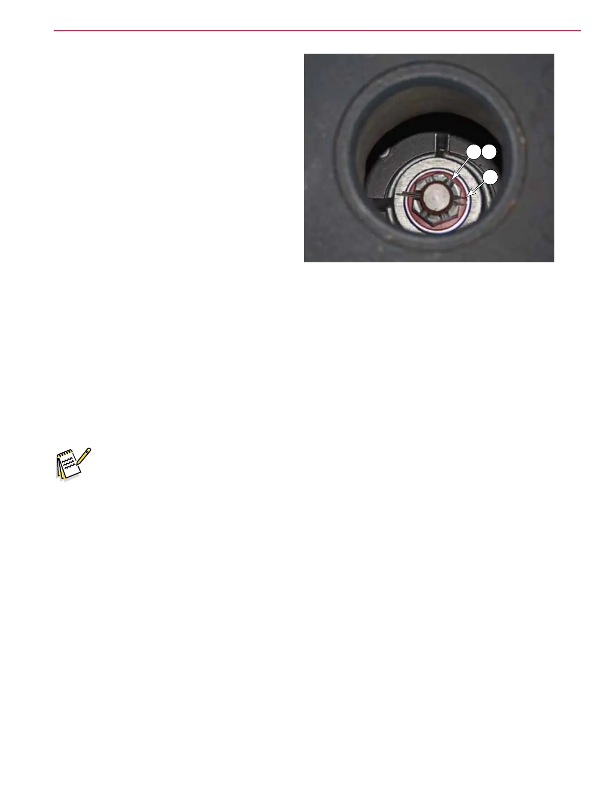
15. Remove the cotter pin (J) from the castle nut
(K).
16. Using a 36 mm socket, remove the castle nut
(K) and washer (L).
17. Slowly begin to raise the machine away from
the drive wheel.
• As the machine is being raised, conrm that
there are no obstructions or wires hung up
on the motor assembly.
• As necessary, support the wheel assembly
with chocks to prevent it from tipping while
you nish raising the machine.
Castle Nut Torque
During reassembly, torque the cast nut according to the following steps.
18. Torque the castle nut to 40 ± 4 lb•ft (54 ± 5.5 N•m)
19. Unscrew the castle nut 20 degrees.
20. Continue to unscrew the nut until the cotter pin hole aligns with the nearest castle nut slot. Do not
exceed a total of 80 degrees of rotation from the torqued position, to achieve this alignment.
21. Install the cotter pin.
Steering Chain Tension
Note: During reattachment of the steering chain, when the drive wheel is pointing straight
forward, one of the spokes of the steering wheel should be pointing straight down.
22. As necessary, turn the inner adjustment nut (F2) clockwise to move it away from the tension block.
23. Tighten the outer adjustment nut (F1) against the tension block to increase the chain tension, until
there is about 1/4 inch (6 mm) deection in the chain at the midpoint between the chain disk and the
steering column sprocket.
24. Tighten the inner adjustment nut (F2) against the tension block by turning it counterclockwise.
K L
J

 Loading...