100Service Manual – SC5000 20 - Drive System
Specications
Parameter Range
Brake Coil Resistance • 54 Ω
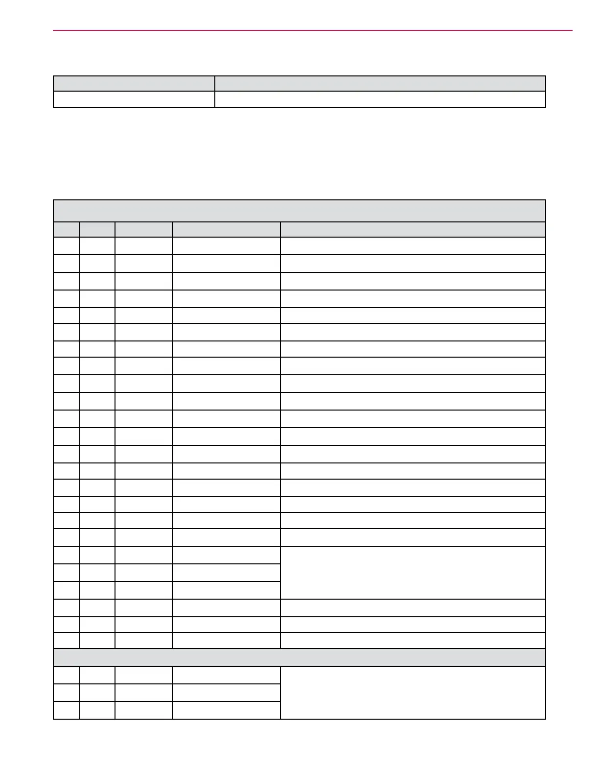
Sample Shop Voltage Measurements
The following table contains some “real world” shop voltage measurements to help you recognize what
“normal” looks like. All voltage values were measured with the black (Negative) voltmeter lead connected to
the main battery negative unless otherwise specied. Most outputs were turned on using the Service/Output
test function.
J5 Drive Controller
Pin# Wire Color Function Observations
1 W165 GRY Potentiometer Gnd 0V
2 W195 YEL CAN-1 H 2.6V
3 W196 GRN CAN-1 L 2.5V
4 W163 BLU-GRY Seat Switch In Open = 0.02V, Seated = B+
6 W164 BLU-YEL E-Stop In Closed = B+, Open/Active = 0.02V
7
8 W193 PNK-YEL Programmer Data N/A
9 W194 PNK-BLU Programmer Clock N/A
10 W166 RED Potentiometer +5V N/A
11
12 W198 RED-ORG +15V Out 13.3V
13 W168 VIO Throttle In (Pot Wiper) 1.0 to 4.0V through full range movement
14
15 W173 VIO Motor Temperature In 1.18V = -114°C (faulty thermocouple)
16
17
18 W189 GRY I/O Ground 0V
19 W188 VIO-GRN Encoder A
AC V = 2.78 at full speed
0 V at park
20 W187 VIO-ORN Encoder B
21 W186 VIO-YEL Encoder C
22 W162 YEL KSI In B+
Motor Lugs
U
0 to 12.7 V AC, from parked to full speed
Machine raised off the ground
V
W

 Loading...