99Service Manual – SC5000 20 - Drive System
Replacement Procedure
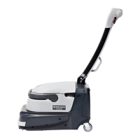
12. Apply anti-seize, such as Loctite 8150, to the
bearing seat of the replacement wheel.
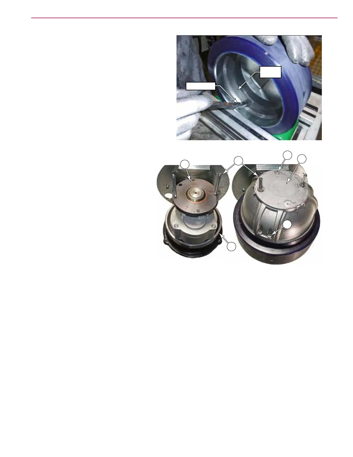
13. Remove the wheel pulling screws (J2) from the
drive housing.
14. Attach the original drive hub (D) to the new
wheel using 6 new screws (F). Torque to
39 Nm (29 lb•ft).
15. Loosely install the two alignment pins (K)
into two of the threaded holes of the drive
disk (G).
16. Slide the drive hub (with the new wheel/
tire) over the alignment pins.
17. Gently tap on the upper portion of the
drive hub (D) to get the wheel started
over the main bearing (H) until the
mounting screws (E) can be started in
their threads.
18. Remove the alignment pins (G), and
replace them with the two remaining
mounting screws (E).
19. In small increments, simultaneously tighten all four mounting screws to pull the drive hub tight to the
drive disk (G).
20. Finish reassembling the machine by reversing the disassembly steps.
Anti-Seize
Bearing
Seat
K
G
E
F
D
H

 Loading...