Control System 37Service Manual – SC3000
Function Electronic Board Lay-Out and Disassembly/Assembly (continued)
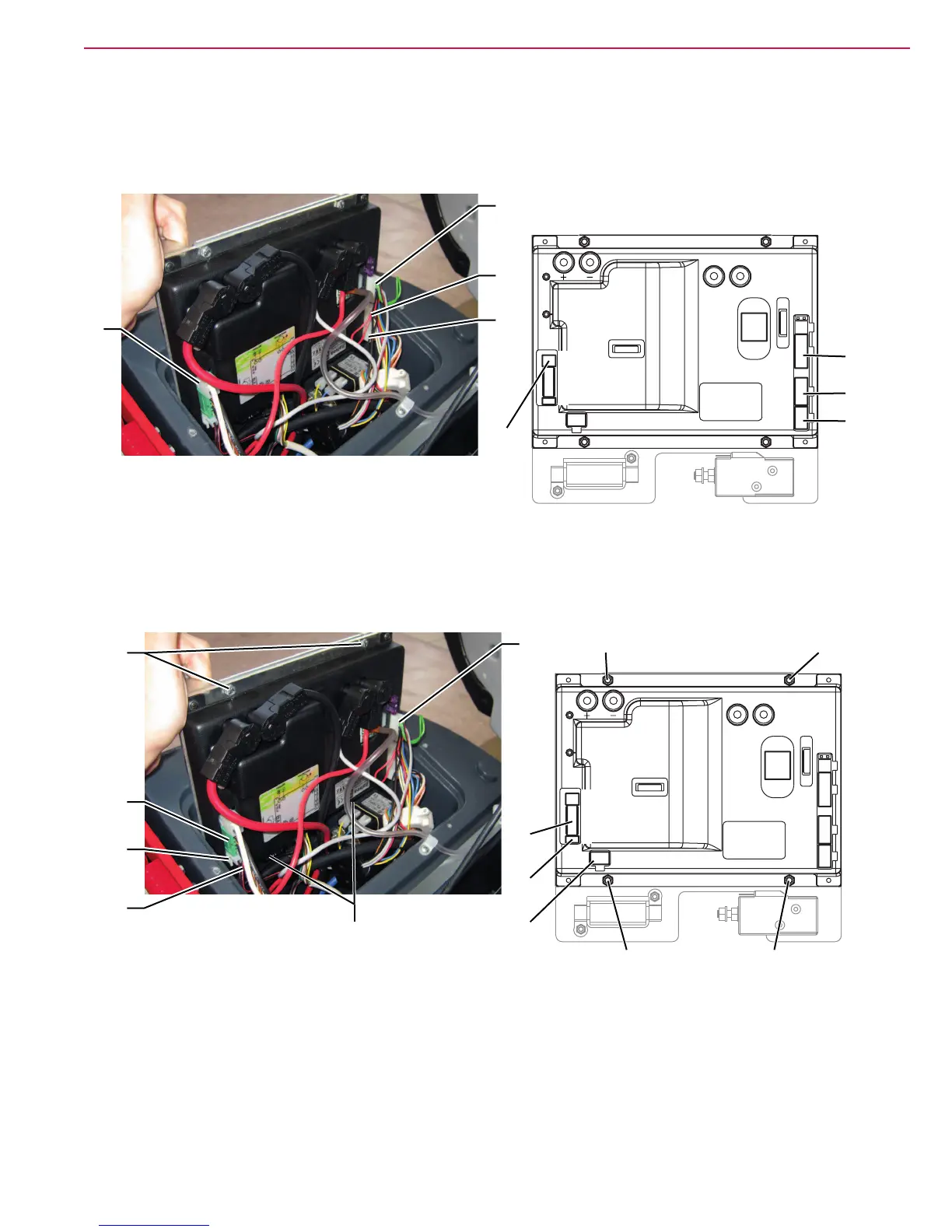
◦ (F) Electrical component wiring harness connection (J1).
◦ (G) Foot board wiring harness connection (J3).
◦ (H) Frame wiring harness connection (J2).
◦ (I) Vacuum system wiring harness connection (VA+ and VA-).
I
G
H
M1
M2
J7A
J7B
J8
J9
J1
J3
J4
J2
J5
J6
VA-
VA+
I
F
G
H
P100553C
◦ (J) Recovery tank wiring harness connection (J6).
◦ (K) Electromagnetic brake wiring harness connection (J5).
◦ (L) Brush deck actuator wiring harness connection (J4).
7. Remove the function electronic board mounting screws (M) from the plate.
J
K
L
M
M
M1
M2
J7A
J7B
J8
J9
J1
J3
J4
J2
J5
J6
VA-
VA+
J
K
L
M M
P100553D
Assembly
8. Assemble the components in the reverse order of disassembly.
 Loading...