168Service Manual – SC401, SCRUBTEC 344 40 - Recovery System
Container and Vacuum Motor Disassembly/Assembly (continues)
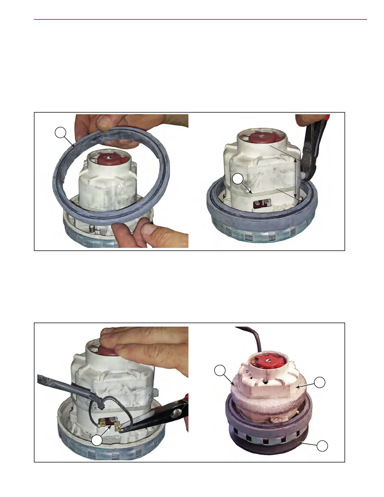
Assembly
13. Position the gasket (Q) on the vacuum system motor. Check that the gasket is reassembled with the
correct orientation (slots).
14. Install the clamp (R). The clamp must be positioned at 2.2 in (55 mm) from the upper surface, around
the entire circumference.
Figure 12:
Q
R
2.2 in (55 mm)
15. Connect the power connections (S) and position the gasket (T) below the vacuum system motor. Check
that the gasket is reassembled with the correct orientation.
16. Position the sponge ring (U) ush against the clamp (R). Check that the wiring is inside the sponge ring
and that the sponge is correctly oriented.
17. Position the clamp (W) together with the wiring.
Figure 13:
S
U
T
W
 Loading...


