Solution System 141Service Manual – SC6500
™
Detergent Tank and Pumps
The Detergent Pumps pump detergent from the Detergent Tank to the tee tting upstream of the solution
pump. The Detergent Pumps get PWM voltage from the A2 Control Board to regulate the speed of the
Detergent Pumps and the subsequent detergent ow.
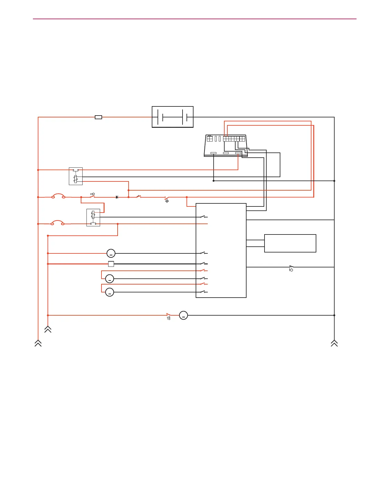
Solution System Wiring Diagram
Circuit Description
Solution System
The Solution Control Pump M12 and solution Solenoid Valve L1 get positive voltage from the Battery when the
load side of contactor K5 is closed. The contactor K5 closes when the A2 Control Board Assembly connects the
K5 coil to battery ground.
A2 Control
Board
Assembly
A3
Switch/Display
Panel Assembly
Fuse, 250 A
36V Battery
A1
Speed
Controller
Motion
8
B-
B+
F4
K7
F1
+
12
-
S1
S2
S3
D1
Key Switch Seat Switch
Battery Interlock Switch
(for roll-out Battery)
Diode
F2
Circuit Breaker, 15 Amp
Circuit Breaker, 3 Amp
K5
4
3
16
15
Direction
Battery Ground
CAN H
CAN L
Solution Control Pump
Solenoid Valve
Detergent Metering Pump
M12
L1
+
-
Detergent Metering Pump
+
-
S5
Solution Empty Switch
(closes when empty)
+
-
Accessory Pump
(optional)
M
M
M
M
M13
M16
M15
B+
Bat -
Bat -
Bat +
Bat +
Bat +
Bat -
Bat -
Bat -
+
-

 Loading...