Wheel System, Traction 189Service Manual – SC6500
™
LED ashes RED once to indicate that the rst digit of the code will follow; the LED then ashes
YELLOW the appropriate number of times for the rst digit. The LED ashes RED twice to indicate
that the second digit of the code will follow; the LED ashes YELLOW the appropriate number of
times for the second digit.
b. The numerical codes used by the yellow LED are listed in the troubleshooting chart, which also lists
possible fault causes and describes the conditions that set and clear each fault.
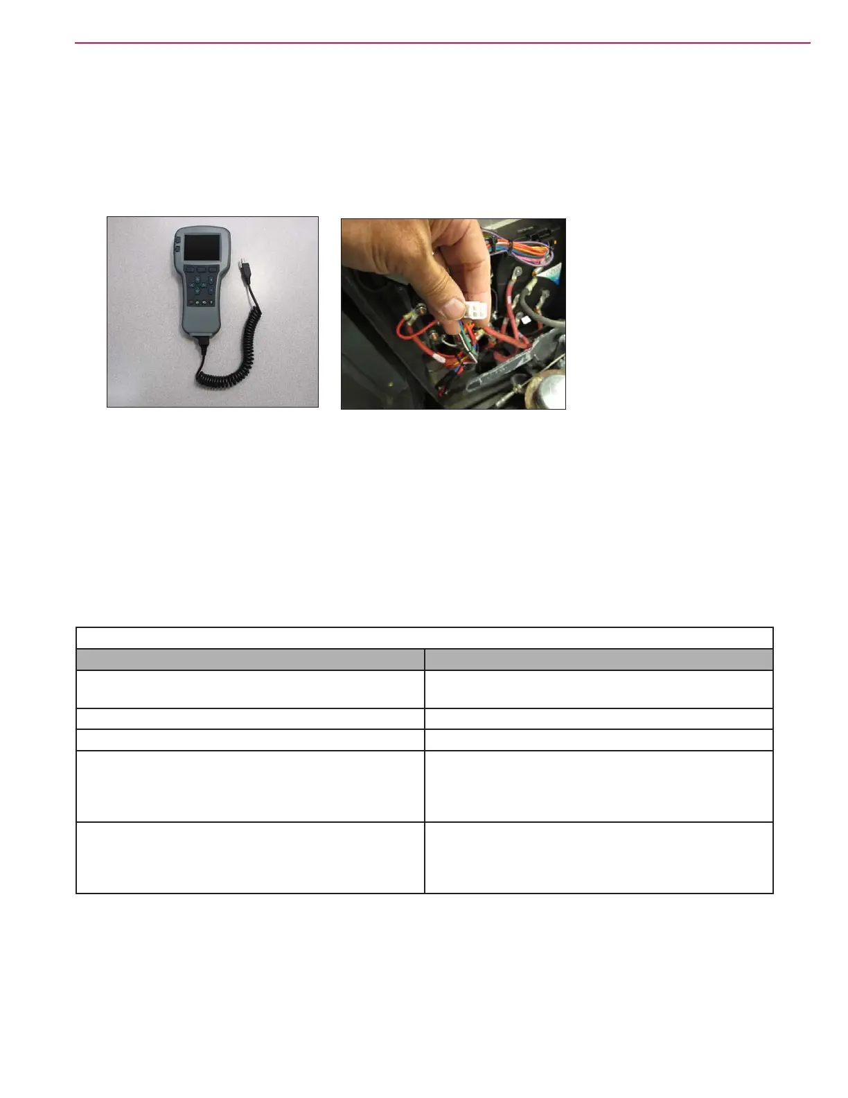
3. Using a Curtis hand-held programmer.
a. The 1313 programmer or the 1311 programmer will display all faults that are currently set as well
as a history of the faults that have been set since the history log was last cleared. The programmer
displays the faults by name. To use the programmer, connect it to the programmer connector located
in the electrical panel by the bank of contactors. Refer to a Curtis industries operator’s manual for
the programmer you are using for more information.
Summary of LED display formats
The status LED has four different display modes, indicating the type of information they are providing.
Types of LED Display
Display Status
Neither LED illuminated Controller is not powered on; or vehicle has dead
battery; or severe damage.
Yellow LED ashing Controller is operating normally.
Yellow and red LEDs both on solid Controller is in Flash program mode.
Red LED on solid No software loaded, or an internal hardware
fault detected by the Supervisor or Primary
microprocessor. Cycle KSI to clear. Reload software
or replace controller if necessary.
Red LED and yellow LED ashing alternately Controller has detected a fault. 2-digit code ashed
by yellow LED identies the specic fault; one or
two ashes by red LED indicate whether rst or
second code digit will follow.
Figure 12: 1313 Programmer Figure 13: Programmer Connector
 Loading...