Wheel System, Traction 206Service Manual – SC6500
™
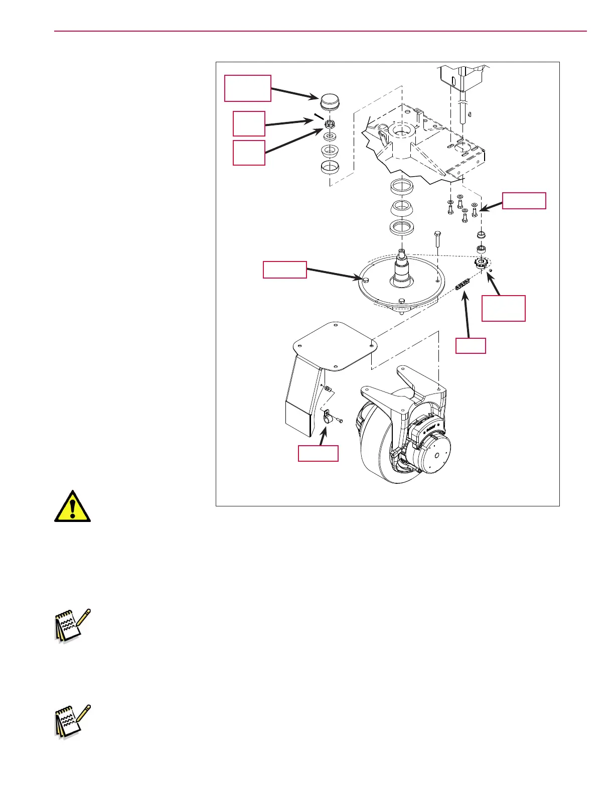
7. Loosen the four Screws from
underneath the front of the
machine and push the lower
steering column toward the
rear of the machine. This
will allow you to separate
the Chain from the Steer
Sprocket
8. Remove the P clamp securing
the wiring harness to the
splash guard and move the
wiring harness aside.
9. Remove the false oor plate
in the operator compartment
(held with three screws) to
allow access to the top spindle
mounting hardware.
10. Remove the Bearing Dust
Cap, Cotter Pin and Castle
Nut from the spindle shaft.
Warning! Never work
under machine without safety stands or blocking to support the machine.
11. Safely jack up or lift up the front of the machine 8-10 inches [20-25 cm] from the center bottom edge of
the solution tank.
12. Carefully guide the wheel motor assembly down and out of its frame opening. Tilt the wheel motor
assembly to the side while raising the machine, then pull it out from underneath the machine.
Note: Be careful not to damage the threads and bearing surfaces when dropping the spindle shaft
down through the frame when removing it from the chassis.
13. Inspect the bearings and seal and replace as needed. If further service work is needed, remove the six
Screws to separate the spindle/steer plate weldment and splash fender from the gear box housing.
14. Reassemble the steering spindle and wheel drive assembly by following the above steps in reverse order.
Note: Tighten the Castle Nut to eliminate any bearing play, then back off the Castle Nut enough
to install a new Cotter Pin.
Chain
Screw (4)
Steer
Sprocket
Bearing
Dust Cap
Cotter
Pin
Castle
Nut
Screw (4)
P-clamp

 Loading...