Control System 58
Service Manual – SC6500
™
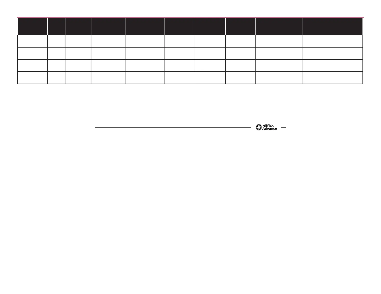
Designation Pin ID
Wire ID/
Color
Description
Signal
Characteristics
Nominal
Value (when
activated)
Reference
To:
Acceptable
Range
Measured Comments
Output J2-20 BLK/WHT
Speed Control -
Mode Sel 2
Voltage 0 or 36V B- (ground)
18.6V
0.03V
Traction on
Traction off
Output J2-21 BLK/ORN
Auxiliary
Contactor
Voltage 0V B- (ground) 0 - 1V
37.4V key off
0.08v key on
Output J2-22 BLU
Vacuum
Contactor
Voltage 0V B- (ground) 0 - 1V
37.4V off
0.13V on
Output J2-23 BLU/WHT
Backup Alarm
(-)
Voltage 0V B- (ground)
12.6V off
0.1V on
* It is difcult to validate the signal using a voltmeter. An LED test light such as a logic probe is a better indicator.
** The Solution Pump (-) line provides a switched ground return for the pump. When the solution pump is on, a 5KHz signal with a varying duty cycle and a peak
voltage of 36 volts will appear between this pin and B+. Measuring with a DC voltmeter will give a signal in the range of 6 to 27 volts. Changing the ow rate
solution bars on the LCD should produce a relative increase or decrease of the meter reading.

 Loading...