87
7 Mechanical Installation
The laser module is designed to be used as either a stand-alone module installed
on a flat surface or as a sub-module which can be slid into a shelf or other
appropriate receptacle. The laser generates heat that must be dissipated. This
section describes how to mount the laser module to ensure optimal function and
heat dissipation.
General
All chassis types must be installed on a level surface that is free from vibrations.
The ambient temperature surrounding the laser should be stable and free from
anything that could cause temperature fluctuations. Temperature changes and
vibrations may affect the laser’s operation and result in abnormal operation.
Caution: For reliable operation, the laser should not be exposed to corrosive
agents or excessive moisture, heat sources or dust.
Standalone mounting
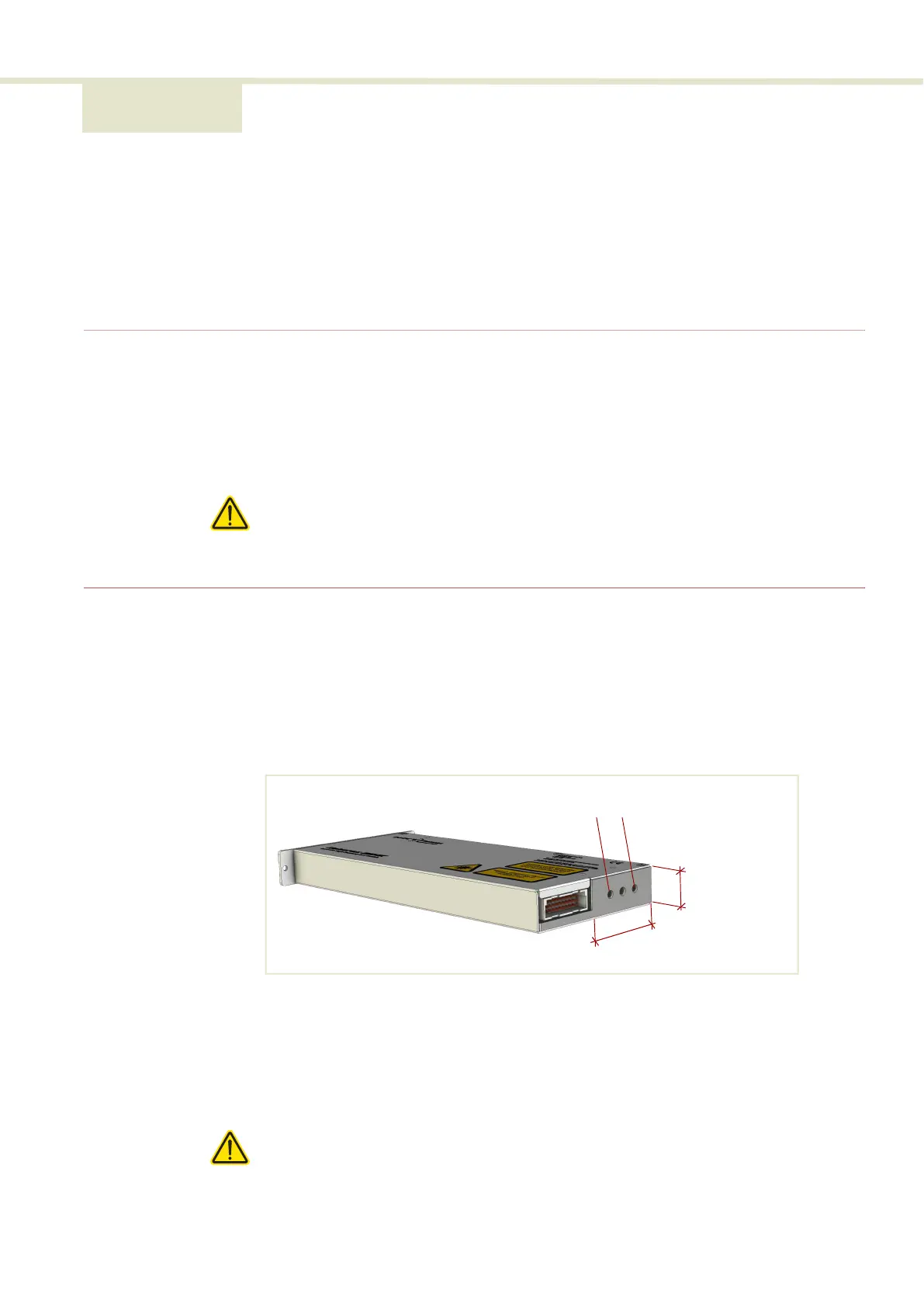
Heat dissipation The heat generating components within the module are thermally connected to a
50 by 20 mm area shown in Figure 60 on the rear panel next to the electrical
interface. To dissipate the heat, A heat sink must be fitted onto this area.
Figure 60 Heat transfer surface - BASIK rear panel
Heat sink
Mount a heat sink to the heat transfer surface of the rear panel as shown in
Figure 61. To mount the heat sink, use the two M4 screw holes on the rear panel
(Figure 60) to fix the heat sink and ensure there is thermal contact with the
module.
Caution: When using the rear panel M4 screw holes, do not turn the fastening
screws more than a maximum of 10 mm into the laser chassis.
20 mm
50 mm
M4 screw holes
 Loading...