Connecting the trigger input or output
96
DIN 41612 female C/3
The DIN 41612 female C/3 connector on the bottom panel of the BASIK interface
board plugs into the electrical interface on the BASIK module.
Connecting the trigger input or output
The modules include a trigger logic input/output signal in the electrical interface
(see Table 19). The trigger signal can be used to either initiate or indicate laser
emission.
Note: For information on how to configure the trigger as either an input or output
using CONTROL see “Trigger” on page 66. For setting the trigger direction using
the SDK, see “Trigger setting input/output” on page 80.
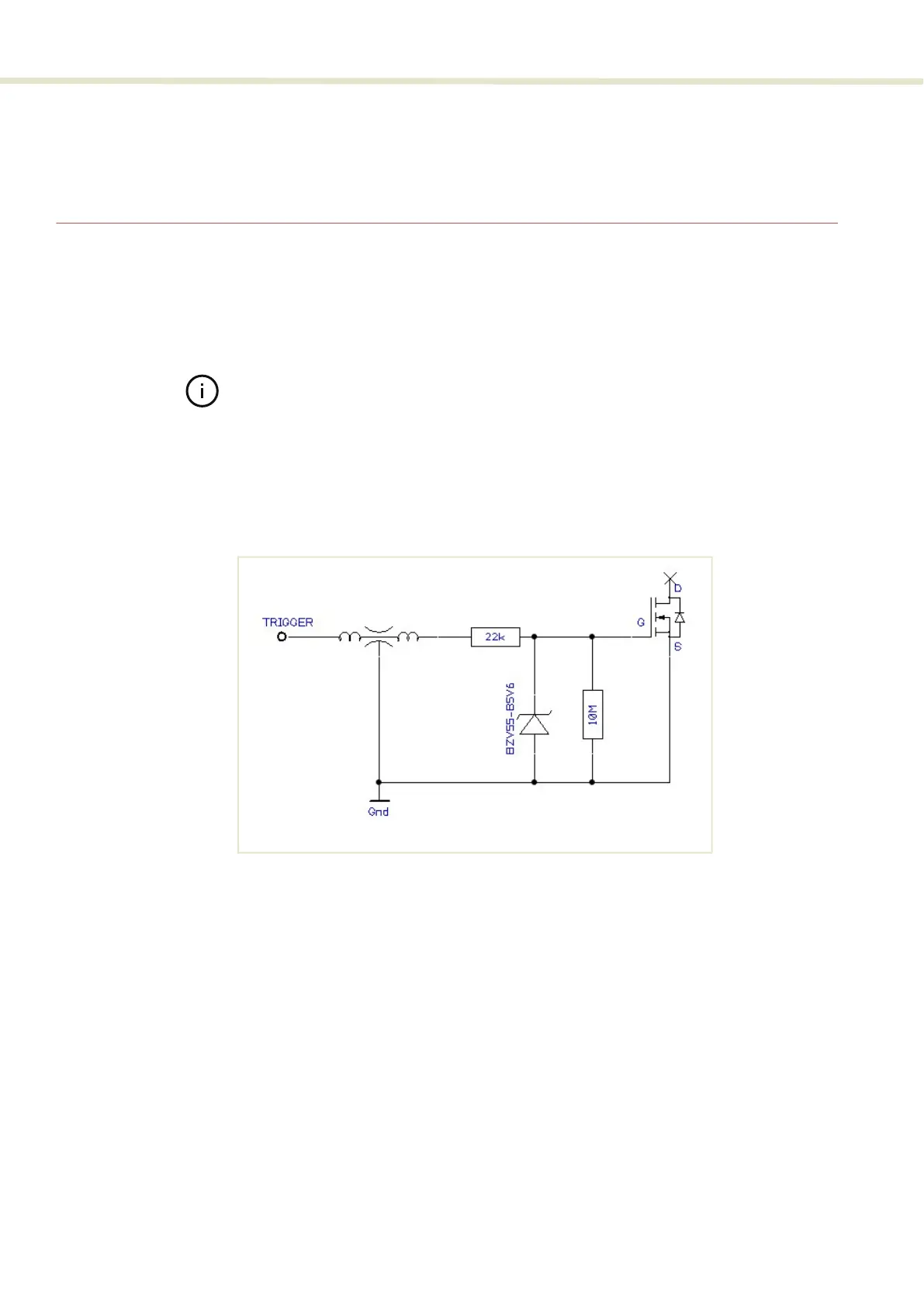
Input trigger When set as an input a positive active high signal must be applied to the trigger
pin to initiate emission. The diagram Figure 67 shows the trigger input.
Figure 67 Trigger input circuit
Output trigger When the trigger feature is set as an output, the trigger pin should be connected
to an external pull-up resistor. The diagram Figure 67 shows the trigger output
circuit.