Connecting the safety interlock
92
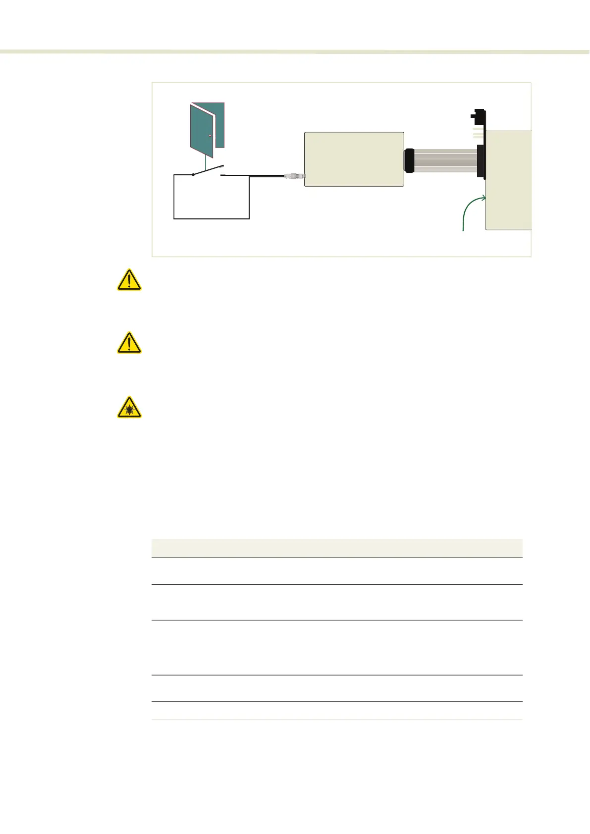
Figure 64 Safety interlock connected to a door switch (open position)
Caution: Do not short-circuit the Interlock input. Short-circuiting the interlock cir-
cumvents safety regulations and NKT Photonics does not take liability for any in-
juries or damage caused by doing so.
Caution: The switch connected to the interlock must be of an approved type.
Further, the switch must be installed in a manner so that its operation cannot be
fixed in the open state using a tool.
Warning: If the interlock is bypassed using the interlock defeater, personnel may
be exposed to hazardous laser radiation. To reduce the risk to personnel, the
person or group responsible for operation of the equipment must undertake a
risk assessment and provide personnel with appropriate personal protective
equipment and safety training.
Connecting an
interlock switch
Follow the steps in Procedure 6 to connect a safety door switch to the interlock
circuit of the laser.
Procedure 6 Connecting the door interlock circuit
RS-485 to USB Adapter
Door
Switch
BASIK module
DB-15 to 16-pin IDC ribbon cable
2-Pin LEMO connector
Emission forbidden
if door switch open
Action
1 Install a switch that opens when the door accessing the laser enclosure is opened. The
switch must comply with safety regulations.
2 Using a cable with a maximum wire length of five meters and at a minimum 26 AWG,
connect the switch to a LEMO connector. For cable lengths longer than five meters, it is
recommended to use shielded cable.
3 Perform a continuity test using a multimeter:
•
First connect the multimeter leads to the interlock plug terminals.
•
Confirm when the enclosure door is closed, the meter shows the circuit as closed.
•
Confirm when the enclosure door opens, the meter shows the circuit as open.
4 Using the DB-15 to IDC 16 pin ribbon cable, connect the RS-485 to USB adapter to the laser
(via the BASIK interface board).
5 Insert the LEMO connector into the LEMO interlock connector of the RS-485 adapter.
2
 Loading...