89
Slide-in mounting
Heat dissipation
Ensure that when the laser is slid in place, the rear heat dissipation area (see
“Heat dissipation” on page 87) makes contact with a suitable surface that can
conduct heat away from the laser.
Aligning the main electrical interface
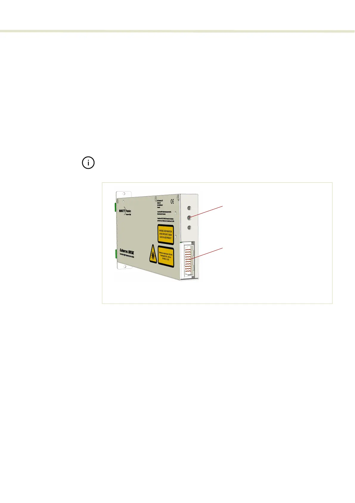
Figure 61 shows a 3.3 mm alignment hole with a depth of 8 mm available in the
center of the heat transfer surface. The hole is designed to mate with an
alignment pin on the back panel of a module mounting rail or receptacle system
to ensure the 30-Pin DIN C/3 electrical interface (see “Main electrical Interface” on
page 24) mates properly. In addition, when the laser chassis slides onto an
alignment pin, it relieves potential mechanical stress from the connector.
Note: The detailed dimensions are shown in Figure 69.
Figure 62 Mounting the laser
Front panel
When using a slide-in type mount, the front panel is equipped with both a handle
and two front panel mounting holes as shown in Figure 63. The handle should be
used when sliding the laser in and out of its mount. Once installed in a rail or
receptacle mount, fix the laser in place, using two screws to fasten the front
panel to a stable surface.
Alignment hole
16 pin IDC connector
(ø: 3.3 mm x depth: 8 mm)
 Loading...